
Instructions
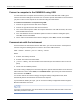
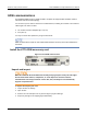
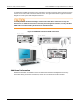
Table Of Contents
- Model DMM6500 6½-Digit Multimeter User's Manual
- 1 Introduction
- 2 Front-panel overview
- 3 Using a remote interface
- 4 Making basic front-panel measurements
- 5 Measuring DC voltage with high accuracy
- 6 Measuring 4-wire resistance with offset compensation
- 7 Scanning temperature at a set time interval
- 8 Grading and binning resistors
- 9 Measuring power using digitizing and TSP-Link
- 10 Troubleshooting FAQs
- About this section
- Where can I find updated drivers?
- Is there any software to help me get started?
- Why did my settings change?
- Why can't the DMM6500 read my USB flash drive?
- How do I upgrade the firmware?
- How do I change the command set?
- How do I save the present state of the instrument?
- How do I save what is displayed on the screen?
- What is the ethernet port number?
- 11 Next steps
- Contact information

Section
3: Using a remote interface Model DMM6500 6½ Digit Multimeter
User's Manual
3-12 DMM6500-900-01 Rev. B / August 2019
To allow many parallel connections to one instrument, stack the connectors. Each connector has two
screws on it to ensure that connections remain secure. The figure below shows a typical connection
diagram for a test system with multiple instruments.
To avoid possible mechanical damage, stack no more than three connectors on any one
instrument. To minimize interference caused by electromagnetic radiation, use only shielded
GPIB cables. Contact Keithley Instruments for shielded cables.
Figure 23: DMM6500 instrument GPIB connections
Additional information
Additional information is available in the KTTI-GPIB Communication and Digital I/O Accessory
Instruction Sheet, part number 0771437XX, where XX is the document revision number.