
Instructions
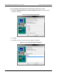
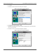
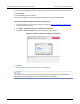
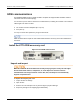
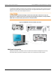
Table Of Contents
- Model DMM6500 6½-Digit Multimeter User's Manual
- 1 Introduction
- 2 Front-panel overview
- 3 Using a remote interface
- 4 Making basic front-panel measurements
- 5 Measuring DC voltage with high accuracy
- 6 Measuring 4-wire resistance with offset compensation
- 7 Scanning temperature at a set time interval
- 8 Grading and binning resistors
- 9 Measuring power using digitizing and TSP-Link
- 10 Troubleshooting FAQs
- About this section
- Where can I find updated drivers?
- Is there any software to help me get started?
- Why did my settings change?
- Why can't the DMM6500 read my USB flash drive?
- How do I upgrade the firmware?
- How do I change the command set?
- How do I save the present state of the instrument?
- How do I save what is displayed on the screen?
- What is the ethernet port number?
- 11 Next steps
- Contact information

Model DMM6500
6½ Digit Multimeter User's Manual Section 3:
Using a remote interface
DMM6500-900-01 Rev. B / August 2019 3-11
Installation
Slot covers must be installed on unused slots to prevent personal contact with high-voltage
circuits. Failure to recognize and observe standard safety precautions could result in
personal injury or death due to electric shock.
To install the communications card:
1. Turn the instrument off and disconnect the power line cord and any other cables connected to the
rear panel.
2. Position the instrument so that you are facing the rear panel.
3. Remove the slot cover plate from the slot on the back of the instrument. Retain the plate and
screws for future use.
4. Align the card with the connector toward the inside edge of the slot and slide the card into the
chassis. For the last ¼ inch, press in firmly to mate the card to the connector.
5. On each side of the card, there is a spring-loaded mounting screw. Tighten these two screws,
either by hand or with a Phillips-head screwdriver, to secure the card in the case. Do not
overtighten.
6. Reconnect the power line cable and any other cables to the rear panel.
7. Turn on the instrument.
Connect GPIB cables to your instrument
To connect a DMM6500 to the GPIB interface, use a cable equipped with standard GPIB connectors,
as shown below.
Figure 22: GPIB connector