
Datasheet


TEK.COM 9
DMM6500 6½-Digit Bench/System Digital Multimeter
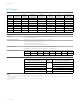
Resistance
Resistance Accuracy ±(% of reading + % of range)
5
Range Resolution
Test Current
(±5%)
Open Circuit
Voltage (±5%)
24 Hours
T
CAL
±1°C
90 Days
T
CAL
±5°C
1 Year
T
CAL
±5°C
2 Years
T
CAL
±5°C
Temperature
Coefficient
1 Ω
6
1 μΩ 10 mA 12.5 V 0.0080 + 0.0200 0.0080 + 0.0200 0.0085 + 0.0200
0.0100 + 0.0200
0.0006 + 0.0010
10 Ω
6
10 μΩ 10 mA 12.5 V 0.0020 + 0.0020 0.0080 + 0.0020 0.0085 + 0.0020
0.0100 + 0.0020
0.0006 + 0.0001
100 Ω 100 μΩ 1 mA 9.2 V 0.0020 + 0.0020 0.0075 + 0.0020 0.0085 + 0.0020
0.0100 + 0.0020
0.0006 + 0.0001
1 kΩ 1 mΩ 1 mA 9.2 V 0.0020 + 0.0006 0.0065 + 0.0006 0.0075 + 0.0006
0.0090 + 0.0006
0.0006 + 0.0001
10 kΩ 10 mΩ 100 μA 12.7 V 0.0020 + 0.0006 0.0065 + 0.0006 0.0075 + 0.0006
0.0090 + 0.0006
0.0006 + 0.0001
100 kΩ 100 mΩ 10 μA 12.5 V 0.0020 + 0.0006 0.0070 + 0.0010 0.0075 + 0.0010
0.0100 + 0.0010
0.0006 + 0.0001
1 MΩ 1 Ω 10 μA 12.5 V 0.0020 + 0.0006 0.0075 + 0.0006 0.0100 + 0.0006
0.0120 + 0.0006
0.0006 + 0.0001
10 MΩ
7
10 Ω 0.7 μA || 10 MΩ 7.1 V 0.0150 + 0.0006 0.0200 + 0.0010 0.0400 + 0.0010
0.0450 + 0.0010
0.0070 + 0.0001
100 MΩ
7
100 Ω 0.7 μA || 10 MΩ 7.1 V 0.0800 + 0.0030 0.2000 + 0.0030 0.2000 + 0.0030
0.2500 + 0.0030
0.0385 + 0.0001
Resistance Measurement Noise Characteristics
8
Measurement
Rate in NPLC Digits
2-wire RMS Noise
Uncertainty
(in % of range + fixed base)
4-wire RMS Noise
Uncertainty, Offset
Compensation OFF
(in % of range + fixed base)
9
4-wire RMS noise
uncertainty, offset
compensation ON
(in % of range + fixed base)
9
5
6.5
0 0 0
1 0 0 0
0.1
10
0.00015 + 0.10 mΩ 0.00020 + 0.20 mΩ 0.00030 + 0.25 mΩ
0.1
5.5
0.00050 + 0.35 mΩ 0.00180 + 2.00 mΩ 0.00350 + 3.50 mΩ
0.01 0.00070 + 0.50 mΩ 0.00260 + 2.50 mΩ 0.00500 + 4.00 mΩ
0.0005 4.5 0.00650 + 3.50 mΩ 0.01000 + 7.00 mΩ 0.01500 + 10.00 mΩ
Resistance Characteristics
Overrange 20% on all ranges
Autozero Off Error Add ±(0.0005% of range + 5 mΩ) within ±1°C and ≤10 minutes since last autozero
Add ±(0.0020% of range + 10 mΩ) within ±5°C and ≤60 minutes since last autozero
Offset Compensation Selectable on 1 Ω, 10 Ω, 100 Ω, 1 k Ω, and 10 kΩ ranges, 4-wire mode only
Maximum 4-wire Lead Resistance 5 Ω per lead for 1 Ω range
10% of range per lead for 10 Ω, 100 Ω, 1 kΩ, and 10 kΩ ranges
1 kΩ per lead for 100 kΩ, 1 MΩ, 10 MΩ, and 100 MΩ
Open Lead Detector Selectable on all ranges, 4-wire mode only; default is off.
Input Protection Input HI 1100 V, Sense HI (SHI) and Sense LO (SLO) 350 V referenced to LO
Scanner Card Additional Contact Resistance
Scanner Card Contact Resistance
2000-SCAN 1 Ω at end of life
20 01-TCSCAN 1 Ω at end of life
Notes
5. Specifications are for 2- and 4-wire resistance. For 2-wire, use relative offset and add 100 mΩ of additional uncertainty. For 4-wire, turn offset compensation on for ≤10 kΩ and off for
>10 k Ω. The 1 Ω range is for 4-wire only.
6. Requires a 10-reading digital filter at 1 PLC or 2-reading digital filter at 5 PLC.
7. Specified for < 10% lead-resistance mismatch at HI and LO.
8. Applies for 1 Ω through 1 MΩ ranges. For 100 Ω range, multiply the listed values by five. Noise values apply to terminals using a low-thermal short for 50 Hz and 60 Hz operation only.
Measurements through a card may introduce additional noise.
9. Open lead detection off.
10. Line sync on.