
Datasheet


Datasheet
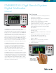
TEK.COM8
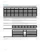
DC Voltage
DC Voltage Accuracy ±(% of reading + % of range)
Range Resolution Input Impedance
24 Hours
T
CAL
±1°C
90 Days
T
CAL
±5°C
1 Year
T
CAL
±5°C
2 Years
T
CAL
±5°C
Temperature
Coefficient
100 mV 100 nV >10 G Ω or 10 MΩ ±1% 0.0015 + 0.0030 0.0025 + 0.0035 0.0030 + 0.0035 0.0035 + 0.0035 0.0001 + 0.0005
1 V 1 μV >10 G Ω or 10 MΩ ±1% 0.0015 + 0.0006 0.0020 + 0.0006 0.0025 + 0.0006 0.0030 + 0.0006 0.0001 + 0.0001
10 V 10 μV >10 G Ω or 10 MΩ ±1% 0.0010 + 0.0004 0.0020 + 0.0005 0.0025 + 0.0005 0.0030 + 0.0005 0.0001 + 0.0001
100 V 100 μV 10 MΩ ±1% 0.0015 + 0.0006 0.0035 + 0.0006 0.0040 + 0.0006 0.0050 + 0.0006 0.0006 + 0.0001
1000 V
1
1 mV 10 MΩ ±1% 0.0020 + 0.0006 0.0035 + 0.0006 0.0040 + 0.0006 0.0050 + 0.0006 0.0006 + 0.0001
Measurement Noise Characteristics and Rejection Ratios
Measurement
Rate in NPLCs Digits
DCV RMS Noise Uncertainty
(in % of range + fixed base)
2
NMRR
3
CMRR
3
5
4
6.5
0 100 dB 140 dB
5 0 60 dB 140 dB
1
4
0 90 dB 140 dB
1 0 60 dB 140 dB
0.1
4
0.00015 + 1 μV 40 dB 120 dB
0.1
5.5
0.00015 + 4 μV -- 120 dB
0.01 0.00030 + 6 μV -- 80 dB
0.0005 4.5 0.00500 + 40 μV -- 80 dB
DC Voltage Characteristics
Overrange 20% on 100 mV, 1 V, 10 V, and 100 V. 1% on 1000 V
ADC Linearity (10 V range) 0.0001% of 10 V range
Input Impedance 100 mV to 10 V Ranges: Selectable: (>10 GΩ or 10 MΩ ±1%) in parallel with <400 pF.
100 V to 1000 V Ranges: 10 MΩ ±1% in parallel with <400 pF
Input Bias Current <50 pA at 23°C
Common Mode Current <600 nA peak-peak at 50 Hz or 60 Hz
Earth Isolation 500 V
peak
>10 G Ω and <300 pF any terminal to chassis
Common Mode Voltage 500 V
peak
LO terminal to chassis maximum
Autozero Off Error Add ±(0.0002% of range + 3 μV) within ±1°C and ≤10 minutes since last autozero
Add ±(0.0010% of range + 10 μV) within ±5°C and ≤60 minutes since last autozero
Input Protection Input HI 1100 V, Sense HI (SHI) and Sense LO (SLO) 350 V referenced to LO
Scanner Card Additional Uncertainties and Maximum Input Signal Levels
Scanner Card Add the Following Uncertainty Maximum Input Signal Level
2000-SCAN 1 μV 110 V
20 01-TCSCAN 1 μV 110 V
Notes
1. For each additional volt over ±500 V, add 0.02 mV of uncertainty.
2. Noise values apply to terminals using a low-thermal short for 50 Hz and 60 Hz operation only. Measurements through a card may introduce additional noise.
3. NMRR for line frequency ±0.1%. For DC common mode and 1 kΩ unbalance on LO terminal, rejection of AC common mode signals is >80 dB for line frequency ±0.1%.
4. Line sync on.