
Datasheet


Datasheet
TEK.COM12
Temperature Characteristics
Thermocouple Conversion ITS-90
Thermocouple Reference Junction External (CJC on 2001-TCSCAN or user-provided with 2000-SCAN) or simulated (fixed)
Open Thermocouple Detection Selectable per channel (open >130 kΩ; default on
Earth Isolation 500 V
PEAK
> 0 GΩ and <300 pF any terminal to chassis
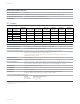
AC Voltage
AC Voltage Accuracy ±(% of reading + % of range)
19
Range Resolution
Calibration
Cycle 3 Hz to 5 Hz 5 Hz to 10 Hz
10 Hz to
20 kHz
20 kHz to
50 kHz
50 kHz to
100 kHz
100 kHz to
300 kHz
100 mV 100 nV
1 V 1 μV
10 V 10 μV
100 V 100 μV
750 V 100 μV
24 hours 1.00 + 0.02 0.35 + 0.02 0.04 + 0.02 0.10 + 0.04 0.55 + 0.08 4.00 + 0.50
90 days 1.00 + 0.03 0.35 + 0.03 0.05 + 0.03 0.11 + 0.0 5 0.60 + 0.08 4.00 + 0.50
1 year 1.00 + 0.03 0.35 + 0.03 0.06 + 0.03 0.12 + 0.05 0.60 + 0.08 4.00 + 0.50
2 years 1.00 + 0.03 0.35 + 0.03 0.07 + 0.03 0.13 + 0.05 0.60 + 0.08 4.00 + 0.50
Temperature Coefficient
0.100 + 0.003 0.035 + 0.003 0.005 + 0.003 0.011 + 0.005 0.060 + 0.08 0.200 + 0.020
AC Voltage Characteristics
Overrange (voltages in V
RMS
) 20% on 100 mV, 1 V, 10 V, and 100 V ranges. 0% for 750 V range
AC Measurement Method AC-coupled digital sampling with anti-alias filter
Crest Factor (excludes sine wave) Crest factors of up to 3:1 at full-scale input or 10:1 maximum, whichever is greater.
Autorange selects optimum range for crest factor up to 10:1.
Accuracy specifications apply to all crest factors and are limited to a product of (crest factor) ×
(fundamental frequency) ≤ 3 kHz.
Volt*Hertz Product ≤8 × 10
7
V*Hz
20
Common Mode Rejection Ratio >70 dB, for 1 kΩ unbalance in LO lead
Detector Bandwidth Setting of 3 Hz, 30 Hz, or 300 Hz sets maximum measurement aperture of 200 ms, 20 ms, or 2 ms,
respectively; only signals with frequency greater than the detector bandwidth are measured.
Input Impedance 1.1 M Ω ±2%, in parallel with <100 pF
Input Protection 110 0 V
peak
Maximum DCV 400 V on any ACV range
ACV Frequency Frequency reading automatically returned in reading buffer when in full buffer mode.
Frequency readings are specified as in the frequency and period table.
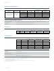
Scanner Card Maximum Input Signal Levels
Module Maximum input signal level
2000-SCAN 125 V
RMS
/175 V
peak
2001-TCSCAN 125 V
RMS
/175 V
peak
Notes
19. Specifications are for sine wave inputs >5% of range.
20. Guaranteed by design.