
User Manual

Model 3760
10-Channel High Current Multiplexer Card User's Manual Section 3:
General operation
3760-900-01 Rev. A / July 2017 3-3
Wiring
Because of the high impedance on the board, take special care when handling and using to prevent
degradation of performance. Handle the board by the edges to avoid contaminating it with dirt or
body oil.
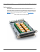
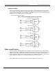
Each channel on the 3760 high-current card consists of a single (2 Form C) relay. The 3760 will
switch any one of the ten signals (inputs) to one output, or switch one signal to any one of ten
outputs.
Hazardous voltages may be present on all input, output, and guard terminals. To prevent
electrical shock that could cause injury or death, never make or break connections to the
3760 while electrical equipment is powered on. Turn off the equipment from the front panel
or disconnect the main power cord from the rear of the 3760 before handling cables. Turn
off or disconnect any external equipment from the card before removing the card from the
mainframe or changing any connections. Precautions must be taken to prevent a shock
hazard by surrounding the test device and any unprotected leads (wiring) with double
insulation for 500 volts, Category I.
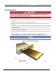
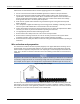
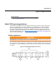
Wiring is accomplished by means of terminal strips as shown on the component layout (see Wire
selection and preparation (on page 3-2)). Each channel has a HI connection, LO connection, and
GUARD connection. Guard is common to all channels. The jumpers (R201-R210) short channel HI to
channel LO when the channel is open. If this is not desired for a channel, remove the jumper. The
3760 is shipped with all jumpers installed.
1. Wiring is accomplished by means of terminal strips on screw terminals.
2. Resistance of the relay contacts (terminals) is less than 150 mΩ.
3. Use wires or cables that are rated for maximum signal levels. The maximum allowable wire size
is No. 16 AWG and the minimum size is No. 26 AWG.
4. Route the wires through the rubber clamp pads located at the rear of the card.
Installation and removal
Once the card is wired, insert it card-edge first into the system switch mainframe by aligning it with the
grooves in the appropriate slot. Make sure it is properly seated into the mainframe connector.
To remove a card, first turn off the mainframe and all other equipment connected to the card. Grasp
the end of the card and carefully pull it out of the mainframe.