www.tek.com/keithley Model 3760 10-Channel High Current Multiplexer Card User’s Manual 3760-900-01 Rev.
Model 3760 10-Channel High Current Multiplexer Card User's Manual © 2017, Keithley Instruments Cleveland, Ohio, U.S.A. All rights reserved. Any unauthorized reproduction, photocopy, or use of the information herein, in whole or in part, without the prior written approval of Keithley Instruments is strictly prohibited. These are the original instructions in English. All Keithley Instruments product names are trademarks or registered trademarks of Keithley Instruments.
Safety precautions The following safety precautions should be observed before using this product and any associated instrumentation. Although some instruments and accessories would normally be used with nonhazardous voltages, there are situations where hazardous conditions may be present. This product is intended for use by personnel who recognize shock hazards and are familiar with the safety precautions required to avoid possible injury.
For safety, instruments and accessories must be used in accordance with the operating instructions. If the instruments or accessories are used in a manner not specified in the operating instructions, the protection provided by the equipment may be impaired. Do not exceed the maximum signal levels of the instruments and accessories. Maximum signal levels are defined in the specifications and operating information and shown on the instrument panels, test fixture panels, and switching cards.
Table of contents Introduction............................................................................................................... 1-1 Your multiplexer card ........................................................................................................... 1-1 System switch / multimeter card compatibility ..................................................................... 1-1 Extended warranty ..............................................................................................
Table of contents Model 3760 10-Channel High Current Multiplexer Card User's Manual Index ...........................................................................................................................
Section 1 Introduction In this section: Your multiplexer card ............................................................... 1-1 System switch / multimeter card compatibility .......................... 1-1 Extended warranty ................................................................... 1-2 Series 3700A documentation ................................................... 1-2 Contact information .................................................................. 1-2 General information......................
Section 1: Introduction Model 3760 10-Channel High Current Multiplexer Card User's Manual Extended warranty Additional years of warranty coverage are available on many products. These valuable contracts protect you from unbudgeted service expenses and provide additional years of protection at a fraction of the price of a repair. Extended warranties are available on new and existing products. Contact your local Keithley Instruments office, sales partner, or distributor for details.
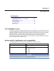
Model 3760 10-Channel High Current Multiplexer Card User's Manual Common mode voltage Environmental conditions Section 1: Introduction 500 V peak Indoor use only Operating: 0 °C to 50 °C (32 °F to 122 °F), 70% relative humidity up to 35 °C (95 °F); derate 3% relative humidity per °C, 35 °C to 50 °C, noncondensing Storage: −25 °C to 65 °C (-13 °F to 149 °F) Altitude: 0 to 2000 m (0 to 6562 feet) above sea level Pollution degree: 2 The 3760 is a high-current multiplexer card with the maximum capabilities
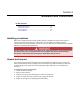
Section 2 Installation and connections In this section: Handling precautions ............................................................... 2-1 Unpack and inspect.................................................................. 2-1 Card connectors ....................................................................... 2-2 Card installation ....................................................................... 2-3 Handling precautions Make sure to handle the 3760 carefully.
Section 2: Installation and connections Model 3760 10-Channel High Current Multiplexer Card User's Manual Card connectors You can make signal input and output connections with the screw terminal connectors on the card. The locations for each channel input and the card output are located outside of the card. All connections will need to be made before the card is installed in the mainframe.
Model 3760 10-Channel High Current Multiplexer Card User's Manual Section 2: Installation and connections Card installation Slot covers must be installed on unused slots to prevent personal contact with high voltage circuits. Failure to recognize and observe standard safety precautions could result in personal injury or death due to electric shock. Perform the following steps to install a switching card into the instrument mainframe: 1.
Section 2: Installation and connections 2-4 Item Description 1 Card guide (part of mainframe) 2 Card 3 Card edge (part of card) 4 Mounting screw (part of card) Model 3760 10-Channel High Current Multiplexer Card User's Manual 3760-900-01 Rev.
Section 3 General operation In this section: General operation .................................................................... 3-1 General operation This section provides information needed to use the 3760 10-channel 2 Form C High-Current Card with the Model 3706A system switch mainframe. Once the card is installed in the mainframe, refer to the Series 3700A System Switch/Multimeter Reference Manual for complete operating instructions.
Section 3: General operation Model 3760 10-Channel High Current Multiplexer Card User's Manual Follow these recommendations before and after applying power to the equipment: 1. Do not exceed the 3760 maximum allowable signal level as defined in the specifications. 2. Do not exceed the 3760 maximum common mode voltage of 500 V peak as defined in the specifications. Exercise extreme caution when a shock hazard is present at the terminals.
Model 3760 10-Channel High Current Multiplexer Card User's Manual Section 3: General operation Wiring Because of the high impedance on the board, take special care when handling and using to prevent degradation of performance. Handle the board by the edges to avoid contaminating it with dirt or body oil. Each channel on the 3760 high-current card consists of a single (2 Form C) relay. The 3760 will switch any one of the ten signals (inputs) to one output, or switch one signal to any one of ten outputs.
Section 4 Operation considerations In this section: Cables ...................................................................................... 4-1 External factors ........................................................................ 4-1 Reactive loads.......................................................................... 4-2 Make a modification .................................................................
Section 4: Operation considerations Model 3760 10-Channel High Current Multiplexer Card User's Manual Reactive loads The 3760 is specified for resistive loads only. Since reactive loads can cause excessive currents and voltages, current surge limiting (for capacitive loads) and voltage clamping (for inductive loads) are required to prevent damaging the relays and external circuitry. Capacitive loads The surge current from a capacitive load must be less than 5 A to protect the relays.
Model 3760 10-Channel High Current Multiplexer Card User's Manual Section 4: Operation considerations Inductive loads Inductive reaction voltage, L(di/dt), must be less than 500 V. Typical clamping circuits are shown in the next figures. Also, consider the maximum load of 100 VA when determining the voltage limit.
Section 5 Typical applications In this section: Model 3760 typical applications ............................................... 5-1 Model 3760 typical applications The 3760 can monitor high current from 10 different devices under test (DUT), switch a high-current source to 10 separate DUTs, or connect multiple DUTs to multiple sources. For more information about some typical applications and graphics showing typical configurations, refer to the Keithley Instruments Switching Handbook.
Section 5: Typical applications Model 3760 10-Channel High Current Multiplexer Card User's Manual Guarded application Non-driven guarded measurements are made with the set up shown in the next figure. The jumper is installed to provide a guard that completely encloses HI and LO. This guards HI and LO from other channels on the card for improved channel isolation.
Model 3760 10-Channel High Current Multiplexer Card User's Manual Section 5: Typical applications Four-wire application Connecting multiple DUTs to one instrument using either a Kelvin technique or external sense as with a Source Measure Unit (SMU), requires two cards operating in four-pole mode. This is shown in the next figure. The Guard and Shield are connected to the card end only and not to the device under test. Also, on the source-measure instrument, the Guard connection is not always made.
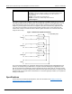
Section 6 Switch terminology In this section: Switch terminology ................................................................... 6-1 Switch terminology The terms Form A, B, or C are used in switch terminology, throughout this manual, and are described as follows: • Form A is simply a single-pole normally-open (SPNO) switch (see next figure) A double-pole switch normally-open is classified as a 2 Form A. • Form B is similar to Form A except that its contacts are normally-closed (see next figure).
Index C Cables • 4-1 Capacitive loads • 4-2 Card connectors • 2-2 Card installation • 2-3 Contact information • 1-2 S D Safety hazards • 3-1 Series 3700A documentation • 1-2 Shielded application • 5-1 Specifications • 1-3 Switch terminology • 6-1 System switch / multimeter card compatibility • 1-1 Driven guard application • 5-2 T E Typical applications • 5-1 Extended warranty • 1-2 External factors • 4-1 U F Four-wire application • 5-3 G General information • 1-2 General operation • 3-1 Guarded a
Specifications are subject to change without notice. All Keithley trademarks and trade names are the property of Keithley Instruments. All other trademarks and trade names are the property of their respective companies. Keithley Instruments Corporate Headquarters • 28775 Aurora Road • Cleveland, Ohio 44139 • 440-248-0400 • Fax: 440-248-6168 • 1-800-935-5595 • www.tek.