
User manual


5-20 Return to Section Topics 3390-900-01 Rev. C / January 2009
Section 5: Waveform Output Operations Model 3390 Arbitrary Waveform Generator User’s Manual
FREQuency:SPAN {<frequency>|MINimum|MAXimum}
MARKer:FREQuency {<frequency>|MINimum|MAXimum}
MARKer {OFF|ON}
SWEep:STATe {OFF|ON}
Use this command to specify the trigger source:
TRIGger:SOURce {IMMediate|EXTernal|BUS}
Use this command to specify whether the sweep is triggered on the rising or the falling edge:
TRIGger:SLOPe {POSitive|NEGative}
Use the following commands to configure the Trig Out signal:
OUTPut:TRIGger:SLOPe {POSitive|NEGative}
OUTPut:TRIGger {OFF|ON}
Burst operation
The burst operation generates a selected waveform with a specified number of cycles (a burst).
Bursts can be triggered internally or manually. Bursts can also be triggered (or gated) externally by
a signal applied to the Trig In/Out, FSK / Burst connector on the rear panel. Sine, ramp, pulse,
square, and arbitrary waveforms can be generated in both triggered and gated burst modes. Noise
can be generated only in the gated burst mode.
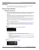
Burst mode
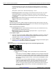
You can select triggered or gated burst mode. Table 5-1 presents the modes and the parameters
affecting each:
•Triggered burst mode: This mode generates a waveform with a specified number of cycles
(burst count) each time it receives a trigger. When the specified number of cycles is
generated, the instrument pauses and waits for next trigger. You can choose to trigger the
bursts using internal source, manual press of the trigger key, external signal at the Trig In/
Out, FSK / Burst connector on the rear panel, or software trigger through the remote
interface (refer to Section 7, Remote Programming for details). Triggered burst mode is the
default burst mode.
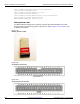
•Gated burst mode: In gated burst mode, the length of a burst is determined by the voltage
level of the external signal applied at the Trig In/Out, FSK / Burst connector on the rear
panel. When the external signal is logic true, the waveform generator outputs a continuous
waveform. When the gate signal is logic false, the output waveform remains at the same
voltage level as the starting burst phase of the selected waveform. The output stops
immediately following a noise burst when the gate signal becomes logic false.
Table 5-1:
Parameters for each burst mode
Burst mode Burst phase Burst count Burst period
External
trigger signal
polarity
Triggered
mode
Internal X X X
External and
Manual
XX
Gated mode X X