
User manual

3390-900-01 Rev. C / January 2009 Return to Section Topics 4-7
Model 3390 Arbitrary Waveform Generator User’s Manual Section 4: Setup Basics
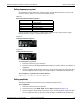
Front panel connections
The Sync and Output connectors are both located on the front panel of the Model 3390.
Controlling the output signal
Signal from the Output connector is controlled by the Output key. The output is disabled by default
at power up; this protects equipment connected to the instrument.
Press the Output key to enable the Output connector. The key is lit when output is enabled.
To enable or disable the output signal from a remote interface:
OUTPut {OFF|ON}
Controlling the sync signal
All Model 3390 output functions (except DC and noise) can be associated with a sync-out signal
(Table 4-2). The sync-out signal is delivered at the Sync connector. The output signal is at a logic
"low" level when the sync signal is disabled. The sync setting is stored in nonvolatile memory and
remains after a remote interface reset, or the instrument power is turned off.
The sync signal has three settings, ON, OFF and AUTO. The AUTO setting enables the
instrument to vary the signal with the associated function.
To set the sync output:
1. Press the Utility key.
2. Press the soft key under Sync. Press the soft key corresponding with your selection (ON,
OFF or AUTO).
To enable or disable the sync signal from a remote interface:
OUTPut:SYNC {OFF|ON}
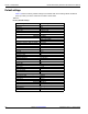
Table 4-2:
Sync signal and function relationships
Function Relationship
Sine, ramp, and pulse
waveforms
Sync signal is a square waveform with a 50% duty cycle.
Relative to 0 volts, the signal is transistor-transistor logic (TTL)
"high" when waveform output is positive and TTL "low" when the
waveform output is negative.
Square waveform Sync signal is a square waveform with the same duty cycle.
Arbitrary waveform Sync signal is a square waveform with a 50% duty cycle. The
signal is TTL "high" when the first waveform point is delivered.
Internally-modulated AM, FM,
PM, and PWM
Sync signal is a square waveform with a 50% duty cycle that is
aligned with the modulating waveform. The signal is TTL "high"
during the first half of the waveform.
Externally-modulated AM,
FM, PM, and PWM
Sync signal is a square waveform with a 50% duty cycle that is
aligned with the carrier waveform.
FSK Sync signal is aligned with shifts in frequency. The signal is TTL
"high" during output of the hop frequency and TTL "low" during
output of the carrier frequency.
Triggered burst The sync signal becomes TTL "high" when the burst is triggered
and transitions to TTL "low" at the end of the specified number of
cycles.
Externally-gated burst The sync signal starts at TTL "high" with the external gate signal
and transitions to TTL "low" at the end of the last cycle.