
User manual


3390-900-01 Rev. C / January 2009 Return to Section Topics 3-3
Model 3390 Arbitrary Waveform Generator User’s Manual Section 3: Rear Panel
Use this command to reset to a zero-phase reference point. This command does not affect the
output waveform:
PHASe:REFerence
Use this command to enable or disable the phase-lock loss error generator. This setting is stored
in volatile memory and will be reset to default (OFF) with a power off:
PHASe:UNLock:ERRor:STATe {OFF|ON}
Power connector
Connect to a grounded AC power outlet using the supplied line cord.
GPIB, USB, and LAN ports
The Model 3390 supports three remote interfaces: Universal serial bus (USB), local area network
(LAN) and general purpose interface bus (GPIB or IEEE-488). Instructions for setting up these
remote interfaces can be found in Section 7, Remote Programming.
For GPIB communication, connect to the GPIB port using an IEEE-488 cable (Keithley
Instruments Model 7007-1 or 7007-2).
Trig In/Out, FSK / Burst connector
This connector routes input and output signals.
Modulation In connector
Modulate the carrier waveform with an external waveform present at the Modulation In connector
on the rear panel (external source must be selected).
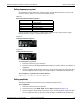
Digital Output/low voltage transistor-transistor logic (LVTTL) port
This parallel interface includes an edge-selectable clock and 16-bit data (for pattern out
operations). The 40-pin cable is used to connect the socket with your board or device.