
User manual

3-2 Return to Section Topics 3390-900-01 Rev. C / January 2009
Section 3: Rear Panel Model 3390 Arbitrary Waveform Generator User’s Manual
Rear panel description
The Keithley Instruments Model 3390 Arbitrary Waveform Generator rear panel is described in this
section (Figure 3-1).
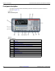
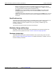
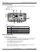
Figure 3-1:
Model 3390 rear panel
Rear panel connections
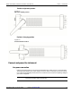
10 MHz Out and In connectors
The 10 MHz Out connector delivers a 10 MHz single-phase signal locked to the internal instrument
clock. The 10 MHz In connector accepts an external 10 MHz clock signal. You can use these
connections to synchronize multiple instruments and control phase offset.
To set up 10 MHz Out and In from a remote interface:
Use this command to specify degrees or radians:
UNIT:ANGLe {DEGree|RADian}
Use this command to specify the phase offset of the output waveform. This value can be set in
degrees or radians as specified by the UNIT:ANGL command:
PHASe {<angle>|MINimum|MAXimum}
Table 3-1:
Rear panel item descriptions
Item Description
1, 2 10 MHz Out and In connectors
3 Vent
4 Power connector
5, 6, 7 GPIB, USB, and LAN ports
8 Trig In/Out, FSK / Burst connector
9 Modulation In connector
10 Digital Output/low voltage transistor-transistor logic (LVTTL) port