
User manual


Model 2700 Multimeter/Switch System User’s Manual Limits and Digital I/O 9-9
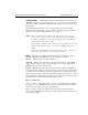
Figure 9-4
Controlling externally powered relays
4.75k
Pull Up Resistor
Pin 9 - Digital Ground
Digital Output
Pin 7 - Diode Clamp
Relay
Coil
Relay
Coil
+
+
-
-
External Power
(+5V to +33V)
External Power
(+5V to +33V)
Model 2700
Transistor Switch
Flyback
Diode
Equivalent Circuit
Digital Output #1
Flyback Diode
Control
Line
33V
+5V