
Data Sheet

DC POWER SUPPLIES
A Greater Measure of Confidence
www.keithley.com
1.888.KEITHLEY
(U.S. only)
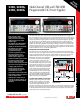
2220, 2220G,
2230, 2230G
Multi-Channel USB and USB/GPIB
Programmable DC Power Supplies
Specifications
2230-30-1, 2230J-30-1,
2230G-30-1, 2230GJ-30-1
2220-30-1, 2220J-30-1,
2220G-30-1, 2220GJ-30-1
DC OUTPUT RATING
Voltage
0 to 30 V 0 to 30 V 0 to 6 V 0 to 30 V 0 to 30 V
Current
0 to 1.5 A 0 to 1.5 A 0 to 5 A 0 to 1.5 A 0 to 1.5 A
MAXIMUM POWER
120 W 90 W
LOAD REGULATION
Voltage
< 0.01% + 3 mV < 0.01% + 3 mV < 0.01% + 3 mV < 0.01% + 3 mV < 0.01% + 3 mV
Current
< 0.01% + 3 mA < 0.01% + 3 mA < 0.01% + 3 mA < 0.01% + 3 mA < 0.01% + 3 mA
LINE REGULATION
Voltage
< 0.01% + 3 mV < 0.01% + 3 mV < 0.01% + 3 mV < 0.01% + 3 mV < 0.01% + 3 mV
Current
< 0.1% + 3 mA < 0.1% + 3 mA < 0.1% + 3 mA < 0.1% + 3 mA < 0.1% + 3 mA
RIPPLE AND NOISE
Voltage (7MHz)
< 1 mV rms
< 3 mV p-p
< 1 mV rms
< 3 mV p-p
< 1 mV rms
< 3 mV p-p
< 1 mV rms
< 3 mV p-p
< 1 mV rms
< 3 mV p-p
Current (20MHz)
< 5 mA rms < 5 mA rms < 6 mA rms < 5 mA rms < 5 mA rms
SETTING RESOLUTION
Voltage
1 mV 1 mV 1 mV 1 mV 1 mV
Current
1 mA 1 mA 1 mA 1 mA 1 mA
SETTING ACCURACY
Voltage
± 0.03% + 10 mV ± 0.03% + 10 mV ± 0.03% + 10 mV ± 0.03% + 10 mV ± 0.03% + 10 mV
Current
± 0.1% + 5 mA ± 0.1% + 5 mA ± 0.1% + 5 mA ± 0.1% + 5 mA ± 0.1% + 5 mA
METER RESOLUTION
Voltage
1 mV 1 mV 1 mV 1 mV 1 mV
Current
1 mA 1 mA 1 mA 1 mA 1 mA
METER ACCURACY
Voltage
± 0.03% + 10 mV ± 0.03% + 10 mV ± 0.03% + 10 mV ± 0.03% + 10 mV ± 0.03% + 10 mV
Current
± 0.1% + 5 mA ± 0.1% + 5 mA ± 0.1% + 5 mA ± 0.1% + 5 mA ± 0.1% + 5 mA
• To save time when repeating tests, instrument
settings can be saved in one of 30 internal
memory locations by simply pressing the Save
button. To recall that setting, just push the
Recall button, and choose the desired setup.
Protection for Your Device-Under-Test
These multi-channel power supplies include
maximum voltage settings that prevent volt-
age from being accidentally adjusted above
user-specified limits. Independent outputs allow
a different limit to be specified for each output
channel. With the numeric keypad, a current
limit can be quickly and precisely specified
before a test is started. In addition, a user-
definable password allows the front panel
to be locked to prevent unwanted adjustment
during critical tests.
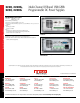
Easy Test Automation
Two interface choices are available to enable
PC control from a user-preferred programming
environment. A USB TMC-compliant device port
is included on all versions of these power sup-
plies. The “G” versions add the GPIB interface
for the flexibility of either USB or GPIB control.
LabView and IVI drivers are provided to facilitate
instrument control, data logging, and analysis.
With these drivers, the power supplies can be
controlled from most commercially-available
software packages such as MatLab. Thus, these
power supplies can be controlled as a single unit
or as part of an automated test system.
APPLICATIONS
Typical applications include:
• Circuit design
• Electrial engineering student labs
• Materials research
• Automated test
ISOLATION VOLTAGE, OUTPUT TO CHASSIS: Any output
can be floated up to 240V (DC + peak AC with AC limited to
a maximum of 3Vpk-pk and a maximum frequency of 60Hz)
relative to earth ground terminal.
ISOLATION VOLTAGE, OUTPUT TO OUTPUT: Any output can
be floated up to 240V (DC + peak AC with AC limited to a
maximum of 3Vpk-pk and a maximum frequency of 60Hz)
relative to any other output terminal.
VOLTAGE TRANSIENT RESPONSE SETTLING TIME, LOAD
CHANGE (typical): <150ms to within 75mV following
a change from 0.1A to 1A.
VOLTAGE TRANSIENT RESPONSE SETTLING TIME, SETTING
CHANGE, RISING (typical): <150ms to within 75mV
following a change from 1V to 11V into a 10W resistor (Ch. 1,
2); from 0.4V to 4V into a 4W resistor (ch. 3.)
VOLTAGE TRANSIENT RESPONSE SETTLING TIME, SETTING
CHANGE, FALLING (typical): <150ms to within 75mV
following a change from 11V to 1V into a 10W resistor (Ch. 1,
2); from 0.4V to 4V into a 4W resistor (ch. 3.)
DISPLAY: Vacuum fluorescent display.
MEMORY: 30 setup memories.
TRACKING AND COMBINATION MODES:
Tracking Mode: Maintains the ratio on the two 30V output
channels that is present when the control is activated.
Combination V1+V2 Series Mode: Deliver up to 60 V when
CH1 and CH2 are wired in series. Meter reads back com-
bined voltage.
Combination I1+12 Parallel Mode: Deliver up to 3 A when
CH1 and CH2 are wired in parallel. Meter reads back
combined current.
REAR PANEL CONNECTIONS: USB Device Port, Type B
connector, USBTMC compatible. 2220G and 2230G versions
include a GPIB interface, IEEE-488.2 compliant.
POWER SOURCE
AC INPUT: Non-“J” versions: Switchable between 120VAC or
240VAC, nominal (different fuse required for each voltage).
“J” Versions: 100VAC, nominal.
FREQUENCY: 50/60Hz
POWER CONSUMPTION:
Dual Channel Versions: 350VA.
Triple Channel Versions: 450VA.
PHYSICAL CHARACTERISTICS
PROTECTIVE BOOTS AND HANDLE INSTALLED:
Height: 105.3mm (4.15 in.)
Width: 241.8mm (9.52 in.)
Depth: 384.0mm (15.12 in.)
PROTECTIVE BOOTS AND HANDLE REMOVED:
Height: 90.7mm (3.57 in.)
Width: 217.2mm (8.55 in.)
Depth: 361.6mm (14.24 in.)
NET WEIGHT:
2220-30-1: 8.2 kg (18 lb.)
2230-30-1: 8.5 kg (19 lb.)
SHIPPING WEIGHT:
2220-30-1: 11 kg (24 lb.)
2230-30-1: 11 kg (24 lb.)
SERVICES AVAILABLE
Model Number*-EW 1 additional year of factory warranty
Model Number-5Y-EW 2 additional years of factory warranty
beyond the standard 3-year warranty
C/Model Number-3Y-STD 3 calibrations within 3 years of purchase
C/Model Number-3Y-DATA 3 (ANSI-Z540-1 compliant)
calibrations within 3 years of purchase
C/Model Number-5Y-STD 5 calibrations within 5 years of purchase
C/Model Number-5Y-DATA 5 (ANSI-Z540-1 compliant)
calibrations within 5 years of purchase
* Replace “Model Number” with a power supply model number.
For example: if the 2230GJ-30-1 is selected, then the part
number for the -EW, one year of additional warranty option,
is 2230GJ-30-1-EW.
NOTE: the “J” versions truncate the “A” in DATA.
Example: C/222GJ-30-1-3Y-DAT
Models 2220 and 2230 specifications
Models 2220 and 2230 specifications