www.keithley.com KI-Tool and KI-Link Software User’s Manual 2110-921-01 Rev.
KI-Tool And KI-Link Software User's Manual © 2013, Keithley Instruments, Inc. Cleveland, Ohio, U.S.A. All rights reserved. Any unauthorized reproduction, photocopy, or use of the information herein, in whole or in part, without the prior written approval of Keithley Instruments, Inc. is strictly prohibited. All Keithley Instruments product names are trademarks or registered trademarks of Keithley Instruments, Inc. Other brand names are trademarks or registered trademarks of their respective holders.
Table of Contents Introduction ............................................................................................................... 1-1 Welcome .............................................................................................................................. 1-1 What is the KI-Tool?............................................................................................................. 1-1 What is the KI-Link? .......................................................................
Section 1 Introduction In this section: Welcome .................................................................................. 1-1 What is the KI-Tool? ................................................................. 1-1 What is the KI-Link? ................................................................. 1-2 System requirements ............................................................... 1-2 Obtaining the software .............................................................
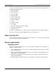
Section 1: Introduction KI-Tool And KI-Link Software User's Manual The KI-Tool software simulates the front-panel operation of a Keithley Instruments digital multimeter, including the following functions: • • • • • • • • • • • • • DC voltage (DCV) AC voltage (ACV) DC current (DCI) AC current (ACI) 2-wire resistance (2Ω) 4-wire resistance (4Ω) Frequency (FREQ) Period Continuity (CONT) Diode ( ) Resistance temperature detectors (TEMP) Thermocouple (TCOUPL) Capacitance ( ) The KI-Tool software allows y
KI-Tool And KI-Link Software User's Manual Section 1: Introduction NI-VISA Runtime TM TM NI-VISA is National Instruments (NI ) implementation of the VISA standard. There are two versions: a full version and a run-time version. The Keithley I/O Layer (KIOL) contains a licensed version of the NI-VISA Run-Time Engine that contains only the binary files (DLLs) that allow the NIVISA drivers to operate.
Section 2 Installing the software In this section: Installing the software .............................................................. 2-1 Connecting instruments to a computer..................................... 2-2 Installing the software To install NI-VISA: Refer to the reference manual for information about installing NI-VISA. The reference manual is located on the CD-ROM that came with your instrument.
Section 2: Installing the software KI-Tool And KI-Link Software User's Manual Connecting instruments to a computer Make sure you install the NI-VISA Runtime before you connect instruments to a computer. Connect the instrument to the computer before starting the KI-Tool software. Using USB A USB cable is shipped with the instrument.
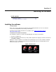
Section 3 KI-Tool In this section: Starting the KI-Tool Software ................................................... 3-1 Workspace ............................................................................... 3-2 Menus ...................................................................................... 3-6 Starting the KI-Tool Software Connect the instruments to the computer first, before starting the KI-Tool software.
Section 3: KI-Tool KI-Tool And KI-Link Software User's Manual Changing the language By default, the KI-Tool software displays menu items in English. You have the option to change the language to Chinese. If you select another language, the KI-Link software will display menus in the selected language. Refer to the About (on page 3-23) topic for information about how to change the language. Workspace The workspace is the environment that appears when you open the KI-Tool software.
KI-Tool And KI-Link Software User's Manual Section 3: KI-Tool (1) Menu bar The menu bar provides menus and buttons to configure and run the KI-Tool software. The menu bar is located at the top of the user interface. Refer to Menus (on page 3-6) for information about the menus on the menu bar. (2) Toolbar The toolbar contains tools to control the KI-Tool software operation and to set up functions. Click the start icon to start plotting data on the graph.
Section 3: KI-Tool KI-Tool And KI-Link Software User's Manual Y-Scale The Y-Scale control allows you to adjust the size of the vertical axis division. Use the Up and Dn (down) buttons to increase and decrease the span of the plots. Offset The Offset control allows you to apply an offset to each data point by adding or subtracting the value entered. Enter the offset value and click the SET button.
KI-Tool And KI-Link Software User's Manual Section 3: KI-Tool Figure 6: Select instrument from Instrument List to display readings 2110-921-01 Rev.
Section 3: KI-Tool KI-Tool And KI-Link Software User's Manual (6) Function Panel Select the function you want the instrument to perform by clicking the desired function button. See the following table for a description of each function. Button Function DCI ACI 4W DC current measurement. AC current measurement. PERIOD DIODE TCOUPL DCV ACV 2W FREQ CONT TEMP CAP 4-wire (Ω 4) resistance measurement. Period measurement. Diode ( ) test. Thermocouple temperature measurement. DC voltage measurement.
KI-Tool And KI-Link Software User's Manual Section 3: KI-Tool Device Settings Use Device Settings to set up the selected instrument. Depending on which model instrument you are setting up, the Device Settings window may have different settings. The following figure shows the Device Settings window for an instrument equipped with second measurement (2ND) function capabilities. Figure 7: Device Settings window (instrument with 2ND function capabilities) 2110-921-01 Rev.
Section 3: KI-Tool KI-Tool And KI-Link Software User's Manual The following figure shows the Device Settings window for an instrument without 2ND function capabilities. Figure 8: Device Settings window (instrument without 2ND function capabilities) (1) Device List Lists the instruments connected to the computer. If you want to view or change an instrument's settings, click to highlight the instrument. (2) Function Lists the functions available for the instrument. To configure a function: 1.
KI-Tool And KI-Link Software User's Manual Section 3: KI-Tool (3) Range or Sensor Lists the ranges available for the function you selected in the list of functions. If you selected TEMP or TCOUPLE, this will list sensors. To make a selection, open the drop-down menu and click the range or sensor. Or, click AUTO to use autorange. (4) Resolution, Filter, Aperture, or Unit Open the drop-down menu and click the appropriate choice for the function you selected.
Section 3: KI-Tool KI-Tool And KI-Link Software User's Manual Reading Settings Use Reading Settings to configure the following KI-Tool software settings: • • • Store the readings from multiple devices simultaneously. Display the readings in the color you select. Save the readings to a record. Reading Mode Select Single Device (on page 3-10) or Multiple Devices (on page 3-11). Single Device Click Single Device to configure the instrument to take readings on one device only.
KI-Tool And KI-Link Software User's Manual Section 3: KI-Tool Multiple Devices The Multiple Device selection is only available when multiple instruments are connected to the computer. The maximum number of devices that can be controlled simultaneously is four. To configure more than one instrument: 1. Select Multiple Devices. The KI-Tool software displays the Reading Settings dialog box. 2. Select the instruments and click Select. 3.
Section 3: KI-Tool KI-Tool And KI-Link Software User's Manual Figure 11: Reading Settings for second instrument 3-12 2110-921-01 Rev.
KI-Tool And KI-Link Software User's Manual Section 3: KI-Tool Change Color Configure the KI-Tool software to display the graphs for each instrument in the color you choose. To select a color: 1. Click Change Color, the KI-Tool software displays the color palette as shown in the following figure. 2. Select the color. 3. Click OK. If a 2ND Change Color button is on the Reading Settings dialog box, repeat steps 1 through 3 to change the 2ND color.
Section 3: KI-Tool KI-Tool And KI-Link Software User's Manual Save Use Save to record readings. You can save up to 10 records. To record readings: 1. Select the Save check box. 2. Select one of the numbered records for recording readings in the drop-down menus. 3. If you are recording from multiple instruments, refer to Multiple Devices (on page 3-11) for information about toggling between the different devices. Figure 13: Select Save to record readings 3-14 2110-921-01 Rev.
KI-Tool And KI-Link Software User's Manual Section 3: KI-Tool The KI-Tool software date and time stamps previously recorded records in the following format: yy / mm / dd -- hh : mm : 00 Where: • yy = last two digits of the year • mm = month • dd = day of the month • hh = hours in 24 hour format • mm = minutes • ss = seconds Refresh If you connect additional instruments to your computer after starting the KI-Tool software, click Refresh to add them to the instrument list.
Section 3: KI-Tool KI-Tool And KI-Link Software User's Manual Figure 14: View Record Record Display The Record Display lists the following information for each reading in the record: • • • • Record number (in the first column) Value - the reading value Value_2ND - the reading value for the 2ND function. If the instrument is not configured for a 2ND function, the field will be blank. If the instrument does not support a 2ND function, the field will not be present.
KI-Tool And KI-Link Software User's Manual Section 3: KI-Tool MAX MIN AVG Displays the following information: • • • MAX - the value of the maximum (highest) reading in the record. MIN - the value of the minimum (lowest) reading in the record. AVG - the average value of all readings in the record. Data Filter The Data Filter allows you to set upper and lower boundaries to sort the readings. To use the data filter: 1. Enter the upper limit in the HI Limiter field. 2.
Section 3: KI-Tool KI-Tool And KI-Link Software User's Manual Figure 15: Chart Record Settings Use the Settings area of the Chart Records window to set up the following charting operations: • • • 3-18 Select a record to chart. Display the records in the color you select. Set the Y-scale for the chart. 2110-921-01 Rev.
KI-Tool And KI-Link Software User's Manual Section 3: KI-Tool The following figure shows the Settings area. Refer to the following topics for descriptions of the settings. Figure 16: Settings Select Record Open the drop-down menu and select a previously saved record you want to chart. Data Quantity This field displays the number of readings in the selected record. Change Color Click the Change Color button to display the color palette.Select the color for the record display.
Section 3: KI-Tool KI-Tool And KI-Link Software User's Manual Graph The KI-Tool software graphs the data and displays the chart. Drawing Use the Drawing button to instruct the KI-Tool software to create the chart based on the selections in the Settings. 2ND Drawing (if equipped) If the record you are charting has a 2ND function measurement, use the 2ND Drawing button to plot the 2ND function measurement readings. Clear Use the Clear button to reset the display to blank.
KI-Tool And KI-Link Software User's Manual Section 3: KI-Tool Multiple Readings Multiple Readings keeps the chart from updating while the instrument is taking readings. The KI-Tool software stores the readings in a file and does not display dynamic curves. Multiple Readings takes a specified number of measurements and puts them into the specified lists. When you select Multiple Readings, stop is enabled while data is being taken. The following figure shows the Multiple Readings dialog box.
Section 3: KI-Tool KI-Tool And KI-Link Software User's Manual Command Control The following figure shows the Command Control dialog box. The following topics describe the fields in the Command Control dialog box. Figure 19: Command Control Device List The Device List drop-down menu lists the instruments connected to the computer. Open the dropdown menu and click the instrument you want to configure, operate, or command. Send String Enter the SCPI commands in the Send String dialog box.
KI-Tool And KI-Link Software User's Manual Section 3: KI-Tool String Received The KI-Tool software displays any information the instrument returns in the String Received display area. Exit Click Exit to close the KI-Tool software. About Use the About menu to view the KI-Tool software version information and select the language. Figure 20: About Multimeter Tool 2110-921-01 Rev.
Section 3: KI-Tool KI-Tool And KI-Link Software User's Manual To select the language: 1. Click the Language tab on the About dialog box. The KI-Link software displays the language list shown in the following figure. Figure 21: KI-Tool language 2. Click the language you want. 3. Click OK to close the About dialog box. 3-24 2110-921-01 Rev.
Section 4 KI-Link In this section: Overview .................................................................................. 4-1 Overview Before you can start using the KI-Link software, you must install the software and connect instruments to your computer. Refer to the Installing the software (on page 2-1) section for information about installing the software.
Section 4: KI-Link KI-Tool And KI-Link Software User's Manual The following message may appear: Figure 23: Message 2. Click OK. If you are using an earlier version of Microsoft Office than Office 2007, the KI-Link software toolbar is visible after Microsoft Excel starts. 3. If you are using Office 2007 or 2010, click the Add-Ins tab. The following figure shows how the KI-Link software toolbar displays in Excel 2010.
KI-Tool And KI-Link Software User's Manual Section 4: KI-Link About the KI-Link software Use the About button on the toolbar to: • • View information about operating system compatibility. Select the language. The default language is English. If you select another language, the KI-Link software will display menus in the selected language. To view information about operating system compatibility: 1. Click the About KI-Link software button.
Section 4: KI-Link KI-Tool And KI-Link Software User's Manual To select the language: 1. Click the Language tab on the About dialog box. The KI-Link software displays the language list shown in the following figure. Figure 26: KI-Tool Micorsoft Excel Add-in language 2. Click the language you want. 3. Click OK to close the About dialog box. 4-4 2110-921-01 Rev.
KI-Tool And KI-Link Software User's Manual Section 4: KI-Link Connect to Device The KI-Link software can only control one instrument at a time. Use the Connect to Device dialog to: • • • Connect instruments Disconnect instruments Search the device list for instruments that are connected To connect an instrument: 1. Click the Connect to Device icon. The KI-Link software displays the Select Device dialog box, shown in the following figure. Figure 27: Select Device dialog box 2110-921-01 Rev.
Section 4: KI-Link KI-Tool And KI-Link Software User's Manual 2. Click the Search button. The KI-Link software displays the Select Device dialog box showing the Identified Instruments on My Computer list, shown in the following figure. Figure 28: Identified Instruments on My Computer list 3. Select the device you want to connect. 4. Click the Connect button.
KI-Tool And KI-Link Software User's Manual Section 4: KI-Link To disconnect an instrument: 1. If the Select Device dialog box is not open, click the Connect to Device icon to open it. Figure 30: Device Connect 2. Click the Disconnect button. After your computer disconnects from the instrument, the KI-Link software removes the Key Lock icon from the selected instrument. 3. You can connect another instrument on the list, or click the OK button to exit the Select Device dialog box. 2110-921-01 Rev.
Section 4: KI-Link KI-Tool And KI-Link Software User's Manual Setup Multimeter Use the Setup Multimeter dialog box to configure the instrument. To configure the instrument: 1. Click the Setup Multimeter icon. The KI-Link software displays the Device Settings dialog box, shown in the following figure. Figure 31: Device Settings dialog box 2. Select a function from the function list. 3.
KI-Tool And KI-Link Software User's Manual Section 4: KI-Link File Access Use the File Access dialog box to save instrument settings to a file and restore them for use. To save settings to a file: 1. Click the File Access icon. The KI-Tool displays the dialog box shown in the following figure. Figure 32: Load Multimeter Setting from File / Save Multimeter Setting to File 2. 3. 4. 5. Select Save Multimeter Settings to File. Click OK. The Windows Save As dialog box opens.
Section 4: KI-Link KI-Tool And KI-Link Software User's Manual Logging Charts Use Logging Charts to set up data logging and display it on a chart. Click the Logging Charts icon. The KI-Link software displays the Set up/Run Logging Worksheet dialog box. This dialog box has two tabs: • • Logging Chart Logging The following figure shows the Logging tab. Refer to the following topics for information about the fields on the Logging tab.
KI-Tool And KI-Link Software User's Manual Section 4: KI-Link If you select At Time, enter the time as follows: 1. Select the date by positioning the cursor in the month, day, or year field and using the up and down arrows to increase or decrease digits. The date format is mm/dd/yyyy. Where: mm = 2-digit month, dd = day, and yyyy = 4-digit year 2. Enter the time in 24-hour format by positioning the cursor in the hours, minutes, or seconds field and entering the digits.
Section 4: KI-Link KI-Tool And KI-Link Software User's Manual Chart Type Select one of the following chart types: • No Chart - Select No Chart to keep the data from appearing on the chart until you click the OK button. • • Graph Strip Chart If you select Strip Chart, enter the number of data points. Refer to the Examples (on page 4-12) topic for information about what the different types of charts look like.
KI-Tool And KI-Link Software User's Manual Section 4: KI-Link Figure 37: Measured data on the same sheet Figure 38: Measured data on different sheets 2110-921-01 Rev.
Section 4: KI-Link KI-Tool And KI-Link Software User's Manual START, PAUSE, and STOP Use the START, PAUSE, and STOP icons to control data capture to the KI-Link software. • • • Use to start. Use to pause. Use to stop. Microsoft Word Starting the KI-Link software add-in for Microsoft Word To start the software: 1. Double-click the KI-LINK Word Add-In icon on the desktop. Word opens. Figure 39: KI-LINK Word Add-In icon 2. The toolbar displays.
Specifications are subject to change without notice. All Keithley trademarks and trade names are the property of Keithley Instruments, Inc. All other trademarks and trade names are the property of their respective companies. Keithley Instruments, Inc. Corporate Headquarters • 28775 Aurora Road • Cleveland, Ohio 44139 • 440-248-0400 • Fax: 440-248-6168 • 1-888-KEITHLEY • www.keithley.