
User manual


Front Panel Operation
3-28 2001-900-01 Rev. K/ August 2010
loop area of the input leads and connect each signal at only
one point.
Thermal EMFs: Thermal emfs (thermoelectric potentials)
are generated by thermal differences between the junctions
of dissimilar metals. These can be large compared to the
signal that the Model 2001 can measure. Thermal emfs can
cause the following conditions:
• Instability or zero offset is much higher than expected.
• The reading is sensitive to (and responds to) tempera-
ture changes. This effect can be demonstrated by touch-
ing the circuit, by placing a heat source near the circuit,
or by a regular pattern of instability (corresponding to
heating and air conditioning systems, or changes in sun-
light).
To minimize the drift caused by thermal emfs, use copper
leads to connect the circuit to the Model 2001. A banana plug
generates a few microvolts. A clean copper conductor such
as #10 bus wire is ideal for this application. The leads to the
input may be shielded or unshielded, as necessary. Refer to
Shielding
Widely varying temperatures within the circuit can also
create thermal emfs. Therefore, maintain constant offset
temperatures to minimize these thermal emfs. A cardboard
box around the circuit under test also helps by minimizing air
currents.
The REL control can be used to null out constant offset
voltages.
Note that additional thermals may be generated by the
optional Model 2001-SCAN scanner card.
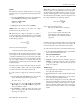
AC voltage offset: The Model 2001, at 5Hd resolution, will
typically display 150 counts of offset on AC volts with the
input shorted. This offset is caused by the offset of the TRMS
converter. This offset will not affect reading accuracy and
should not be zeroed out using the rel feature. The following
equation expresses how this offset (V
OFFSET
) is added to the
signal input (V
IN
):
Example: Range = 2VAC
Offset = 150 counts (1.5mV)
Input = 200mV RMS
The offset is seen as the last digit which is not displayed.
Therefore, the offset is negligible. If the rel feature were used
to zero the display, the 150 counts of offset would be sub-
tracted from V
IN
resulting in an error of 150 counts in the dis-
played reading.
3.4.2 DC and AC current
DC current measurements
The Model 2001 can make normal DC current measurements
between 10pA and 2.1A. Assuming “bench reset” conditions
(see paragraph 3.12.1), the basic procedure is as follows:
1. Connect the test leads to the AMPS and INPUT LO ter-
minals of the Model 2001. Either the front or rear inputs
can be used; place the INPUTS button in the appropriate
position.
2. Select the DCI function.
3. Select a range consistent with the expected current. For
automatic range selection, press the AUTO key. The
AUTO annunciator denotes whether auto-ranging is en-
abled.
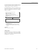
4. Connect the test leads to the source as shown in Figure
3-11.
CAUTION
Do not apply more than 2.1A, 250V to
the AMPS input, or the amps protection
fuse will blow.
5. Observe the display. If the “Overflow” message is
shown, select a higher range until a normal reading is
displayed. Always use the lowest possible range for the
best resolution.
6. Take a reading from the display.
Displayed reading V
IN
2
+ V
OFFSET
2
=
Display reading 200mV
2
+1.5mV
2
=
= 0.04V 2.25 10
-6
V+
= .200005V