
User manual


IEEE-488 Reference
2001-900-01 Rev. K / August 2010 4-69
40 END
Line 10 Sets the upper limit of LIMIT 1 to 10, and then queries the programmed limit.
Line 20 Addresses the Model 2001 to talk.
Line 30 Displays the upper limit of LIMIT 1 (10).
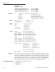
:SOURce <NRf>
:CALCulate3:LIMit[1]:UPPer:SOURce <NRf> Specify pattern; upper LIMIT 1 failure
:CALCulate3:LIMit[1]:LOWer:SOURce <NRf> Specify pattern; lower LIMIT 1 failure
:CALCulate3:LIMit2:UPPer:SOURce <NRf> Specify pattern; upper LIMIT 2 failure
:CALCulate3:LIMit2:LOWer:SOURce <NRf> Specify pattern; lower LIMIT 2 failure
Parameter <NRf> = 0 to 15 Specify digital pattern for output port
Formats :calc3:lim:upp:sour <NRf>
:calc3:lim:low:sour <NRf>
:calc3:lim2:upp:sour <NRf>
:calc3:lim2:low:sour <NRf>
Defaults Power-up Saved power-on setup
*RST 0
:SYSTem:PRESet 0
Query :SOURce? Query source value for specified limit
Short-form formats: :calc3:lim:upp:sour?
:calc3:lim:low:sour?
:calc3:lim2:upp:sour?
:calc3:lim2:low:sour?
Response message: 0 to 15
Description These commands are used to specify which line(s) of the Digital Output Port will go true when a limit
test failure occurs. The first failure in the test sequence determines the digital output pattern. Subsequent
failures in the test sequence will not change the digital output pattern on the output port.
Each output line is assigned a decimal weight as follows:
Digital Output Decimal Weight
Line #1 1
Line #2 2
Line #3 4
Line #4 8
The parameter value for the digital pattern is determined by adding the decimal weights of the desired
output lines. For example, if you want output lines #2 and #3 to go true when the upper limit of LIMIT
1 is the first failure in the test sequence, use a parameter value of 6 (2+4) as follows:
:calc3:lim:upp:sour 6