
User manual


IEEE-488 Reference
4-16 2001-900-01 Rev. K / August 2010
The following SCPI query command can be used to read the
Measurement Condition Register:
:STATus:MEASurement:CONDition?
The Measurement Condition Register and the Transition Fil-
ter are used to set the bits of the Measurement Event Regis-
ter. The Transition Filter is discussed next.
Measurement Transition Filter The transition filter is
made up of two 16-bit registers that are programmed by the
user. It is used to specify which transition (0 to 1, or 1 to 0)
in the Measurement Condition Register will set the corre-
sponding bit in the Measurement Event Register.
The filter can be programmed for positive transitions (PTR),
negative transitions (NTR) or both. When an event bit is pro-
grammed for a positive transition, the event bit in the Mea-
surement Event Register will set when the corresponding bit
in the Measurement Condition Register changes from 0 to 1.
Conversely, when programmed for a negative transition, the
bit in the status register will set when the corresponding bit
in the condition register changes from 1 to 0.
The individual bits of the transition filter registers can be set
or cleared by using the following SCPI commands:
:STATus:MEASurement:PTR <NRf>
:STATus:MEASurement:NTR <NRf>
The transition filter registers can be read at any time by using
the following SCPI query commands:
:STATus:MEASurement:PTR?
:STATus:MEASurement:NTR?
Reading a transition filter register using the above query
commands does not affect the contents of the register.
The following operations will set (1) all the bits of the PTR
register and clear (0) all the bits of the NTR register:
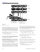
cáÖìêÉ=QJNN
Measurement event status
(B15 - B12) (B10) (B9) (B8) (B7) (B6)
RAV
(B5) (B4) (B3)
OR
BFL = Buffer Full
BHF = Buffer Half Full
BAV = Buffer Available
& = Logical AND
OR = Logical OR
(B2)
LL1
(B1) (B0)
(B15 - B12) (B10) (B9)
BHF
(B8)
BAV
(B7) (B6)
RAV
(B5) (B4) (B3) (B2)
LL1
(B1) (B0)
Measurement Event
Register
(B15 - B12)
Measurement Event
Enable
Register
To Measurement
Summary Bit
(MSB) of Status
Byte Register.
(See Figure 4-13)
&
&
PTR = Positive Transition Filter
NTR = Negative Transition Filter
PTR Measurement
NTR Transition Filter
(B15 - B12) (B10) (B9) (B8) (B7) (B6)
RAV
(B5) (B4) (B3)
(B2)
LL1
(B1) (B0)
Measurement
Condition Register
BFL HL2 HL1 ROF
BFL HL2 HL1 ROF
BFL HL2 ROF
&
&
&
&
BHF BAV LL2
BHF BAV LL2
LL2 HL1
&
&
&
(B10) (B9)
BHF
(B8)
BAV
(B7) (B6)
RAV
(B5) (B4) (B3) (B2)
LL1
(B1) (B0)
BFL HL2 ROFLL2 HL1
RAV = Reading Available
HL2 = High Limit 2
LL2 = Low Limit 2
HL1 = High Limit 1
LL1 = Low Limit 1
ROF = Reading Overflow
BPT
(B11)
BPT
(B11)
BPT
(B11)
&
BPT
(B11)
BPT = Buffer Pretriggered