
User manual


IEEE-488 Reference
2001-900-01 Rev. K/ August 2010 4-15
The transition filter registers can be read at any time by using
the following SCPI query commands:
:STATus:OPERation:TRIGger:PTRansi
tion?
:STATus:OPERation:TRIGger:NTRansi
tion?
Reading a transition filter register using the above query
commands does not affect the contents of the register.
The following operations will set (1) all the bits of the PTR
register and reset (0) all the bits of the NTR register:
1. Cycling power.
2. Sending the :STATus:PRESet command.
3. Sending the :STATus:OPERation:TRIGger:PTR 65535
and :STATus:OPERation:TRIGger:NTR 0 commands.
Trigger Event Register This is a latched, read-only reg-
ister whose bits are set by the Trigger Condition Register and
Transition Filter. Once a bit in this register is set, it will re-
main set (latched) until the register is cleared by a specific
clearing operation. The bits of this register are logically
ANDed with the bits of the Trigger Event Enable Register
and applied to an OR gate. The output of the OR gate is ap-
plied to bit B5 (Waiting for Trigger) of the Operation Condi-
tion Register.
The following SCPI query command can be used to read the
Trigger Event Register:
:STATus:OPERation:TRIGger:EVENt?
Reading this register using the above SCPI command clears
the register. The following list summarizes all operations
that will clear the Trigger Event Register:
1. Cycling power.
2. Sending the *CLS common command.
3. Sending the :STATus:OPERation:TRIGger? query
command.
Trigger Event Enable Register This register is pro-
grammed by the user and serves as a mask for the Trigger
Event Register. When masked, a set bit (B1) in the Trigger
Event Register cannot set bit B5 (Waiting for Trigger) of the
Operation Condition Register. Conversely, when unmasked,
a set bit (B1) in the Trigger Event Register will set bit B5 of
the Operation Condition Register.
Bit B1 in the Trigger Event Register is masked when the cor-
responding bit (B1) in the Trigger Event Enable Register is
cleared (0). When the masked bit of the Trigger Event Reg-
ister sets, it is ANDed with the corresponding cleared bit in
the Trigger Event Enable Register. The logic “0” output of
the AND gate is applied to the input of the OR gate and thus,
cannot set bit B5 of the Operation Condition Register.
Bit B1 in the Trigger Event Register is unmasked when the
corresponding bit (B1) in the Trigger Event Enable Register
is set (1). When the unmasked bit of the Trigger Event Reg-
ister sets, it is ANDed with the corresponding set bit in the
Trigger Event Enable Register. The logic “1” output of the
AND gate is applied to the input of the OR gate and thus, will
set bit B5 of the Operation Condition Register.
Bit B1 of the Trigger Event Enable Register can be set or
cleared by using the following SCPI command:
:STATus:OPERation:TRIGger:ENABle
<NRf>
The following SCPI query command can be used to read the
Trigger Event Enable Register:
:STATus:OPERation:TRIGger:ENABle?
Reading this register using the above SCPI command will
not clear the register. The following list summarizes opera-
tions that will clear the Trigger Event Enable Register:
1. Cycling power.
2. Sending the :STATus:OPERation:TRIGger:ENABle 0
command.
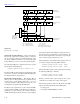
4.6.6 Measurement event status
The reporting of measurement events is controlled by a set of
16-bit registers; the Measurement Event Condition Register,
the Transition Filter, the Measurement Event Status Register
and the Measurement Event Enable Register. cáÖìêÉ= QJNN
shows how these registers are structured. Each of the bits that
is used in these registers represent a measurement event.
Descriptions of the measurement event bits are provided in
paragraph 4.21.
The measurement status registers are controlled by the
:STATus:MEASurement commands in the :STATus
subsystem (see paragraph 4.21).
Measurement Condition Register This is a real-time 16-
bit read-only register that constantly updates to reflect the
current operating conditions of the Model 2001. For exam-
ple, when the trace buffer becomes full, bit B9 (BFL) of this
register will be set. When the buffer is not full, bit B9 will
clear.