
User manual


IEEE-488 Reference
4-14 2001-900-01 Rev. K / August 2010
the instrument is in (or has exited) the measure layer of op-
eration. An explanation of the Model 2001 operation process
is provided in paragraph 4.7. The various registers used for
trigger event status are described as follows. Note that these
registers are controlled by the :STATus:OPERation:TRIGger
commands of the :STATus subsystem (see paragraph 4.21).
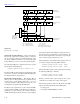
Trigger Condition Register This is a real-time 16-bit
read-only register that constantly updates to reflect the trig-
ger layer status of the instrument. If bit B1 is set, the instru-
ment is in the trigger layer (measure layer) of operation.
The following SCPI query command can be used to read the
Trigger Condition Register:
:STATus:OPERation:TRIGger:CONDiti
on?
The Trigger Condition Register and the Transition Filter are
used to set bit B1 of the Trigger Event Register. The Transi-
tion Filter is discussed next.
Trigger Event Transition Filter The transition filter is
made up of two 16-bit registers that are programmed by the
user. It is used to specify which transition (0 to 1, or 1 to 0)
of bit B1 in the Trigger Condition Register will set bit B1 in
the Trigger Event Register.
The filter can be programmed for positive transitions (PTR),
negative transitions (NTR) or both. When an event bit is pro-
grammed for a positive transition, the event bit in the Trigger
Event Register will set when the corresponding bit in the
Trigger Condition Register changes from 0 to 1. Conversely,
when programmed for a negative transition, the bit in the sta-
tus register will set when the corresponding bit in the condi-
tion register changes from 1 to 0.
The transition filter registers can be set or cleared by using
the following SCPI commands:
:STATus:OPERation:TRIGger:PTRansi
tion <NRf>
:STATus:OPERation:TRIGger:NTRansi
tion <NRf>
(B14 - B2)
(B15)
(B1) (B0)
OR
Trigger
Condition Register
Trigger Event
Enable Register
Seq 1 = Sequence 1 (Set bit indicates that the
2001 is in the trigger layer of Sequence 1)
& = Logical AND
OR = Logical OR
PTR = Positive Transition Register
NTR = Negative Transition Register
&
&
0
Seq1
(B14 - B2)
(B15)
(B1) (B0)
0
Seq1
(B14 - B2)
(B15)
(B1) (B0)
0
Always
Zero
Seq1
PTR
NTR
Trigger
Transition Filter
Trigger Event
Register
(B14 - B2)
(B15) (B1) (B0)
Seq1
To Waiting for Trigger
Bit (Trig) of Operation
Event Condition Register
(See Figure 4-7).
cáÖìêÉ=QJNM
Trigger event status