
User manual


Front Panel Operation
2001-900-01 Rev. K/ August 2010 3-79
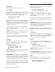
low by the Model 7001, the leading negative-going edge
triggers the Model 2001 to measure DUT #1 (point E). Note
that the multimeter holds the trigger line low. After the
measurement is complete, The Model 2001 releases the
trigger line (point F) and then loops back to point A where it
waits for another input trigger.
When the Model 2001 releases the trigger line, the leading
positive-going edge triggers the Model 7001 to close the
next channel in the scan. This pulls the trigger line low,
triggering the Model 2001 to measure the next DUT. The
process continues until all ten channels are scanned and
measured.
3.8 Buffer
The Model 2001 has a buffer to store reading data. It can
acquire readings at two different rates (normal and burst
modes). The maximum possible number of stored readings
depends on the installed memory option and the user-
programmable data group. (See Table 3-29.)
A full data group includes the readings, units, channel#,
reading#, time-stamp, and status (overflow). A compact data
cáÖìêÉ=PJPV
Operation mode for semi-synchronous Trigger Link example
Idle
Bypass
B
Wait for
Trigger Link
Trigger
Scan
Channel
C
Pull Trigger
Line Low
D
No
Scanned
10
Channels
?
Yes
7001
Make
Measurement
Made
10
Measurements
?
2001Press STEP to start scan
Arm
A
Wait for
Trigger Link
Trigger
E
Release,
Trigger Line
F
No
Yes
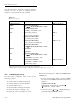
q~ÄäÉ=PJPM
Reading storage options
Memory
Data group
Full Compact Type
Standard
MEM1 option
MEM2 option
250
1400
6000
850
7000
30000
Volatile
Non-volatile
Non-volatile