
User manual


Front Panel Operation
3-78 2001-900-01 Rev. K/ August 2010
Scan source = Immediate*
Scan count = Infinite*
Scan trigger control = Acceptor*
Measure layer:
Measure source = TrigLink
Trigger link mode = Semi-synchronous
Semi-sync line = #1*
Measure count = 10
Measure trigger control = Acceptor*
* Indicates that the setting is the BENCH RESET (and
factory) default condition.
Model 7001:
Idle state:
Reset = :INIT:CONT OFF*
Scan list = 1!1-1!10,
Arm layer:
Arm spacing = Immediate*
Arm count = 1*
Arm trigger control = Acceptor*
Scan layer:
Scan spacing = Immediate*
Number of scans = 1
Scan trigger control = Acceptor*
Channel layer:
Channel spacing = TrigLink
Trigger link mode = Semi-synchronous
Semi-sync line = #1
Number of channels = Use Scanlist length*
Channel trigger control = Source*
* Indicates that the setting is the RESET (and factory)
default condition.
To run the test and store the readings in the Model 2001,
press STORE on the multimeter, enter the desired number of
readings (ten), and press ENTER. The Model 2001 waits
(with the asterisk annunciator lit) for a Trigger Link trigger
from the Model 7001. Press STEP on the Model 7001 to start
the scan.
The following explanation on operation is referenced to the
operation model shown in Figure 3-39.
The BENCH RESET condition arms the Model 2001
and places multimeter operation at point A in the flowchart,
where it is waiting for a Trigger Link trigger. Note that since
both the arm layer and scan layer are programmed for
Immediate Source, operation immediately drops down to the
measure layer at point A.
Pressing STEP takes the Model 7001 out of the idle state
and places operation at point B in the flowchart. Since both
the arm layer and scan layers are programmed for Immediate
Spacing, operation drops down to the Channel Layer at point
B.
Since Channel Trigger Source is set to Source, the scan
does not wait at point B for a trigger. Instead, it bypasses
“Wait for Trigger Link Trigger” and closes the first channel
(point C). Note that the Bypass is in effect only on the first
pass through the model.
After the relay settles, the Model 7001 pulls down the
Trigger Link trigger line (point D). Since the instrument is
programmed to scan ten channels, operation loops back up to
point B, where it waits for an input trigger. Note that Bypass
is no longer in effect.
and Remember that the Model 2001 operation is at
point A waiting for a trigger. When the trigger line is pulled
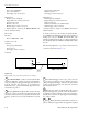
cáÖìêÉ=PJPU
Trigger Link connections (semi-synchronous example)
Trigger
Link
7001 Switch System
Trigger Link
Cable
(8501)
IN
OUT
Line #1
Trigger
Link
2001 Multimeter
IN OUT
A
B
C
D
E
F