
User manual


Front Panel Operation
2001-900-01 Rev. K/ August 2010 3-69
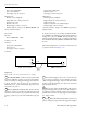
trigger bus. The 8-pin micro-DIN sockets used for the
Trigger Link are shown in Figure 3-28.
NOTE
The two rear panel Trigger Link connec-
tors are actually connected in parallel. It
does not matter which connector you use
when connecting the Trigger Link to an-
other instrument.
In general, Trigger Link input triggers to the Model 2001 are
used to control the measure operation. For the Model 2001 to
respond to Trigger Link compatible triggers, the appropriate
layers of the trigger model must be programmed for it. For
example, if you want Trigger Link input triggers to control
the measuring process, you must program Measure Source
for TRIGLINK trigger events. Typically, a Trigger Link
output trigger from the Model 2001 would be used to trigger
a scanner to close the next channel.
There are two modes of operation for Trigger Link:
asynchronous and semi-synchronous. In the asynchronous
mode, separate lines are used for input and output triggers; in
the semi-synchronous mode, the same line is used for both
input and output triggers.
Asynchronous operation
In the asynchronous operating mode, Trigger Link functions
fundamentally in the same manner as External Triggering
(see paragraph 3.7.6). Like External Triggering, the
asynchronous mode uses separate lines for input and output
triggers. Also, the asynchronous mode uses the same TTL-
compatible pulses as External Triggering. The specifications
for the input and output trigger signals of asynchronous
mode are shown in Figure 3-23 and Figure 3-25,
respectively.
For typical asynchronous Trigger Link operation, the
measure layer is configured with Measure Source set to
TRIGLINK and Triggerlink mode set to
ASYNCHRONOUS. You must also select input and output
lines for the measure layer. Input and output triggers can be
set to any of the six lines, but they cannot use the same line.
For example, if you select line #1 for input triggers, then
output triggers must use one of the other five lines (#2
through #6).
During operation in the measure layer, each Trigger Link
input trigger makes a measurement. After the user-
programmed DELAY and the measurement settling time, the
Model 2001 outputs a Trigger Link completion pulse
(typically to a scanner to close the next channel). The
measure layer is configured using the CONFIG-TRIG menu
(see paragraph 3.7.2).
The scan layer and/or arm layer can also be programmed for
Trigger Link, where Scan Source is set to TRIGLINK, and
Arm Source is set to TRIGLINK. When using Trigger Link
in these layers, you must also select input and output lines as
you did in the measure layer. Keep in mind that you can use
the same lines in the Scan and arm layers as selected in the
measure layer.
Asynchronous Trigger Link example #1
In a typical test system, you may want to close a channel and
then measure the DUT connected to the channel with a
multimeter. Such a test system is shown in Figure 3-29,
which uses a Model 2001 Multimeter to measure ten DUTs
switched by a Model 7011 multiplexer card in a Model 7001
Switch System.
The Trigger Link connections for this test system are shown
in Figure 3-30. Trigger Link of the Model 2001 is connected
to Trigger Link of the Model 7001 Switch System. Notice
that only one Trigger Link cable is needed.
TRIGGER LINK
IN OUT
21
5
43
8
7
6
21
5
43
8
7
6
Pin Trigger Link Line
1 Line #1
2 Line #2
3 Line #3
4 Line #4
5 Line #5
6 Line #6
7 Digital Common
8 Digital Common
cáÖìêÉ=PJOU
Trigger link connectors