™ *DOES NOT INCLUDE MOUNTING PLATE OWNER’S MANUAL MANUEL DE L’UTILISATEUR / MANUAL DEL PROPIETARIO MODEL / MODÈLE / MODELO: KV8.5S 12V DC ELECTRIC WINCH TREUIL ÉLECTRIQUE 12 Vcc. / CABRESTANTE ELÉCTRICO DE 12 V CC ! CAUTION! / ATTENTION! / PRECAUCIÓN! ! READ AND UNDERSTAND THIS MANUAL BEFORE INSTALLATION AND OPERATION OF THIS PRODUCT. VEUILLEZ LIRE ET VOUS FAMILIARISER AVEC CE MANUEL AVANT L’INSTALLATION ET LA MISE EN SERVICE DU PRODUIT.
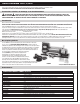
KV8.5S 8,500 lbs. 12 Volt DC ELECTRIC WINCH Designed for Vehicle Recovery, Vehicle Trailers and General Winching Applications. THIS PRODUCT IS NOT INTENDED FOR LIFTING/HOISTING Assembly & Operating Instructions ! CAUTION ! PLEASE READ ALL SAFETY PRECAUTIONS AND WARNINGS BEFORE INSTALLING AND USING THE WINCH! IF YOU HAVE ANY QUESTIONS PLEASE CONTACT OUR CUSTOMER SERVICE DEPARTMENT LISTED BELOW. Introduction Thank you for purchasing your KEEPER® Winch.
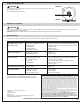
12V DC PERFORMANCE - MODEL KV8.5S Line Pull Lbs. (kg) Line Speed FPM (MPM) 0 2,000 (907) 4,000 (1,814) 6,000 (2,722) 8,000 (3,629) 8,500 (3,856) Motor Amp Draw 21 (6.4) 56 16.6 (5.1) 146 12.2 (3.7) 184 9.8 (3.0) 242 8.1 (2.5) 284 4.2 (1.3) 292 Rolling Load Capacities (1st Layer) SLOPE* 10% (4.5o) 20% (9o) 40% (18o) 60% (27o) 100% (45o) Lbs. 42,713 28,909 18,318 14,144 10,965 Kgs.
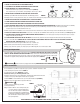
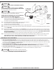
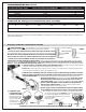
12. NEVER USE YOUR WINCH FOR LIFTING OR MOVING PEOPLE! 13. YOUR WINCH IS NOT INTENDED FOR OVERHEAD HOISTING OPERATIONS. 14. AVOID CONTINUOUS PULLS FROM EXTREME ANGLES. This will cause the wire rope to pile up on one end of the drum (FIGURE 6). This can jam the wire rope in the Winch, causing damage to the wire rope or Winch. Right Wrong 15. NEVER OBSCURE THE WARNING INSTRUCTION LABELS ON THE WINCH. 16. Always operate Winch with an unobstructed view of the Winching operation. FIGURE 6 17.
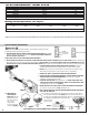
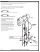
Winch Installation Correct installation of your Winch is required for proper operation. Installation should be on a flat surface following the bolt pattern shown in FIGURE 1. Read and follow directions carefully to ensure proper Winch alignment and trouble free operation. This Winch MUST be mounted with the synthetic rope in the under-wind direction (FIGURE 8). MUST use only genuine Keeper Winch replacement Rope. ! WARNING ! Improper mounting could damage your Winch and void your warranty.
Winch Installation (Continued) B. Take the end of the rope without the hook thimble and place it through the hawse and pass it under the winch through the hole in the drum. Pull enough rope through the hole so that it almost reaches the entire length of the drum. C. Use an adhesive tape to hold the end of the rope to the drum. D. You are now ready to wind the rope onto the drum. 8-10 wraps must remain on the drum at all times to keep the rope from slipping off the drum under tension.
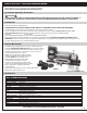
! ! WARNING USE ONLY 3/8” -16 UNC BOLT AND NUTS WITH MINIMUM ISO GRADE 8.8. ! ! WARNING Batteries contain gases, which are flammable and explosive. WEAR EYE PROTECTION DURING INSTALLATION AND REMOVE ALL METAL JEWELRY. Do not lean over battery while making connections. ! ! WARNING Red 2GA Positive Battery Terminal Lead Ensure that the wiring harness does not interfere or come in contact with any hot or moving engine, suspension, steering, braking or exhaust parts.
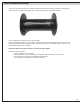
Replacing The Wire Rope ! WARNING ! Winch Drum Never Substitute a heavier or lighter wire rope. Never use rope made of any other materials other than wire or approved synthetic winch rope. Use only Synthetic Winch Rope, 85’ X 3/8” FIGURE 13 Maintenance & Repair ! WARNING ! Before each use, check mounting bolts for tightness, inspect cable for damage. Inspect remote control assembly for any damage. Periodically use a clean, dry towel to remove dirt and debris from winch housing.
TREUIL ÉLECTRIQUE 12 Vcc, 8,5S kV Conçu pour le dépannage de véhicule, les remorques de véhicule et les applications générales nécessitant un treuil. CE PRODUIT N’EST PAS DESTINÉ AUX OPÉRATIONS DE LEVAGE/GRUTAGE Instructions relatives au montage et au fonctionnement ! ATTENTION ! VEUILLEZ LIRE TOUTES LES RECOMMANDATIONS DE PRÉCAUTIONS ET TOUS LES AVERTISSEMENTS AVANT D’INSTALLER ET D’UTILISER LE TREUIL ! POUR TOUTES QUESTIONS, VEUILLEZ VOUS ADRESSER AU SERVICE APRÈS-VENTE INDIQUÉ CI-DESSOUS.
PERFORMANCES EN 12 Vcc Force de traction en ligne – kg/(lb) Vitesse de déroulement en ligne MPM/(FPM) 0 2,000 (907) 4,000 (1,814) 6,000 (2,722) 8,000 (3,629) 8,500 (3,856) Consommation (ampères) du moteur 21 (6.4) 56 16.6 (5.1) 146 12.2 (3.7) 184 9.8 (3.0) 242 8.1 (2.5) 284 4.2 (1.
12. N’UTILISEZ JAMAIS VOTRE TREUIL POUR SOULEVER OU DÉPLACER DES PERSONNES ! FIGURE 6 13. LE TREUIL N’EST PAS CONÇU POUR LES OPÉRATIONS DE LEVAGE AÉRIEN. 14. ÉVITER LES OPÉRATIONS DE TRACTION EN CONTINU EN CONFIGURATION ANGULAIRE EXTRÊME. CORRECT INCORRECT Cela entraîne l’accumulation des enroulements de câble sur un seul côté du tambour (FIGURE 6). Cela peut bloquer le câble métallique dans le treuil et endommager le câble ou le treuil. 15.
Installation du treuil Une installation adéquate du treuil est nécessaire pour assurer le bon fonctionnement. L'installation doit être effectuée sur une surface plate en suivant le modèle de pose des boulons illustré à la FIGURE 1. Lisez et suivez soigneusement les instructions pour vous assurer d’un bon alignement du treuil et d'un fonctionnement sans problème. Ce treuil DOIT être monté avec le câble enroulé par-dessous (FIGURE 8).
Installation du treuil (suite) B. Saisir l’extrémité de la corde sans le crochet à chape et la faire passer à travers le chaumard puis sous le treuil à travers le trou pratiqué dans le tambour. Tirer une longueur de corde suffisante à travers le trou pour qu’elle atteigne presque la longueur totale du tambour. C. Fixer l’extrémité de la corde sur le tambour avec du ruban adhésif. D. On peut alors enrouler la corde autour du tambour.
! AVERTISSEMENT ! UTILISEZ UNIQUEMENT DES BOULONS AVEC ÉCROUS, AYANT UN PAS DE 3/8 po - 16 UNC (UNIFIED NATIONAL COARSE) (À GROS FILET), DE QUALITÉ MINIMALE ISO 8.8. ! AVERTISSEMENT ! Les batteries contiennent des gaz inflammables et explosifs. PORTEZ DES LUNETTES DE PROTECTION PENDANT L’INSTALLATION ET ENLEVEZ TOUS VOS BIJOUX OU ÉLÉMENTS Fil rouge 2GA de la MÉTALLIQUES. Ne vous penchez pas au-dessus de la batterie pendant borne positive de la batterie que vous effectuez les raccordements.
REMPLACEMENT DU CÂBLE MÉTALLIQUE ! AVERTISSEMENT Tambour du treuil ! Ne jamais remplacer le câble en lui substituant un câble plus lourd ou plus léger. N’utilisez jamais de câble fabriqué en d’autres matériaux que l’acier. N’utilisez que du câble en acier galvanisé, de 26 m de long x 9,5 mm de diamètre (85 pieds X 3/8 po).
KW8.5S CABRESTANTE ELÉCTRICO DE 12 V CC Diseñado para la recuperación de automóviles, remolques de vehículos y aplicaciones generales del cabrestante. ESTE PRODUCTO NO ESTÁ DISEÑADO PARA LEVANTAR/ELEVAR Instrucciones de ensamblado y de funcionamiento ! PRECAUCIÓN ! ¡SÍRVASE LEER TODAS LAS PRECAUCIONES Y ADVERTENCIAS ANTES DE INSTALAR Y USAR EL CABRESTANTE! SI TIENE ALGUNA PREGUNTA SÍRVASE CONTACTAR A NUESTRO DEPARTAMENTO DE SERVICIO AL CLIENTE INDICADO MÁS ABAJO.
RENDIMIENTO DE 12 V Tracción del cable en lb (kg) Velocidad del cable en pies/min (m/min) 0 2,000 (907) 4,000 (1,814) 6,000 (2,722) 8,000 (3,629) 8,500 (3,856) Consumo de corriente del motor 21 (6.4) 56 16.6 (5.1) 146 12.2 (3.7) 184 9.8 (3.0) 242 8.1 (2.5) 284 4.2 (1.3) 292 Capacidades de carga rodante (1ra capa) PENDIENTE* 10% (4.
12. ¡NUNCA UTILICE SU CABRESTANTE PARA ELEVAR O MOVER A PERSONAS! FIGURA 6 13. SU CABRESTANTE NO ESTÁ DISEÑADO PARA OPERACIONES DE LEVANTAR POR ARRIBA. 14. EVITE JALAR CONTINUAMENTE EN ÁNGULOS EXTREMOS. Esto causará que el cable de acero se apile en un extremo del tambor (FIGURA 6). Esto puede atascar el cable de acero en el Cabrestante, lo cual daña al cable de acero o al Cabrestante. CORRECTO EQUIVOCADO 15. NUNCA OSCUREZCA LAS ETIQUETAS DE INSTRUCCIÓN DE ADVERTENCIAS EN EL CABRESTANTE. 16.
Instalación del cabrestante Se requiere instalar correctamente su cabrestante para que funcione apropiadamente. La instalación deberá ser en una superficie plana siguiendo el patrón de pernos que se muestra en la FIGURA 1. Lea y siga las instrucciones cuidadosamente para asegurarse de la alineación adecuada del cabrestante y su operación sin problemas. El cabrestante DEBE estar montado con el cable de acero en dirección de enrollado inferior (FIGURA 8).
Instalación del cabrestante (continuación) B. Tome el extremo de la cuerda sin el guardacabos de anillo y páselo por el pasacabos y por abajo del cabrestante a través del agujero en el tambor. Tire suficiente cuerda a través del agujero de manera tal que casi alcance toda la longitud del tambor. C. Use cinta adhesiva para retener el extremo de la cuerda contra el tambor. D. Ahora ya se puede enrollar la cuerda sobre el tambor.
! ADVERTENCIA ! UTILICE ÚNICAMENTE PERNOS Y TUERCAS TIPO UNC DE 3/8”-16 CON GRADO ISO MÍNIMO DE 8.8. ! ADVERTENCIA ! Los acumuladores contienen gases que son inflamables y explosivos. UTILICE PROTECCIÓN DE LOS OJOS DURANTE LA INSTALACIÓN Y QUÍTESE TODA LA JOYERIA DE METAL. Conductor Rojo de No se recargue sobre el acumulador al hacer las conexiones.
CÓMO REEMPLAZAR EL CABLE DE ACERO Tambor del cabrestante Nunca sustituya con un cable de acero más pesado o más liviano. Nunca use cables hechos de otros materiales que no sea acero. Use únicamente Cable de Acero Galvanizado de 26 m x 9.5 mm (85’ x 3/8”) ! ADVERTENCIA ! FIGURA 12 Mantenimiento y reparación ! ADVERTENCIA ! Antes de cada uso, revise los pernos de montaje para verificar que están firmemente apretados e inspeccione el cable para verificar si está dañado.