EXCALIBUR 1000X EXCALIBUR 1000XE EXCALIBUR 5000 INSTRUCTION MANUAL BEDIENUNGSANLEITUNG MANUEL D’INSTRUCTIONS MANUAL DE INSTRUCCIONES MANUAL DE INSTRUCCIONES Single language version and parts diagrams can be down loaded from www.keencut.co.uk Versionen in den einzelnen Sprachen und Schaubilder der Teile sind als Download auf www.keencut.co.uk erhältlich. La version et les schémas des pièces en une seule langue peuvent être téléchargés depuis www.keencut.co.uk KC-EX FEB09 En www.keencut.co.
1 Contents 2 Packing list 2.1 Unpacking your machine 3 Assembly 3.1 3.2 3.3 3.4 3.5 3.6 Adjusting the Legs Preparing to fit the Squaring arm Fitting the Squaring arm Fitting the Wall mounting bracket Fitting the Free standing kit Fitting the Backing panels 4 Squaring 4.1 4.2 Checking your machine for squareness Adjusting the squareness 5 Calibration 5.1 5.2 5.3 Calibrating the vertical square Calibrating the Squaring arm scale Fitting the Sight-line strip 6 Operation 6.1 6.2 6.
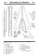
2.1 Unpacking your Machine 2.1 NOTE: When lifting the main body from the box, DO NOT lift using the black handles on the cutters. 1. 2. 3. 4. 5. 6. 7. 8. 9. 10. Main body Squaring arm Left large back panel Left small back panel Right large back panel Right small back panel Wall mounting bracket Measuring rules Spare sight-line strips Plastic rivets * 11. M8 screws 12. Hexagon wrenches 2.0, 2.5, 3.0, 4.0, 5.0, 6.0mm 13. Left hand production stop 14.
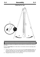
3.1 Assembly 3.1 Adjusting the Legs The first stages of assembly are carried out with the machine laying on the floor. NOTE: When lifting the main body from the box do not lift using the black handles on the cutters. Remove the Main body from the box and lay it on the floor, remove the packaging from the bottom end. 1. 2. Slacken the bottom two screws on each leg using the 5mm Hexagon wrench and extend the telescopic parts to the desired length.
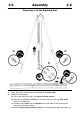
3.2 Assembly 3.2 Preparing to fit the Squaring Arm 1. 2. Move the lower cutting head to the middle of the Main body. Remove the following: A. One screw from each leg, using 5mm Hexagon wrench. B. Two sets of Hexagon headed bolts, washers and nuts from the Main body using 17mm Spanners. C. Remove small Screw and two Washers from the back of the squaring arm using 3mm hexagon wrench. D. Slide off Right hand production stop (this will need to be replaced further on).
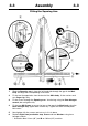
3.3 Assembly 3.3 Fitting the Squaring Arm 1. 2. 3. 4. 5. 6. Slide the Squaring arm in from the left hand side through the gap in the Main body and align the corresponding screw holes. Fit the two Hexagon bolts from the back of the Main body, fit the washers and nuts finger tight only. Fit the screws through the Squaring arm * into the leg using the 5mm Hexagon wrench, do not tighten fully.
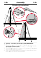
3.4 Assembly 3.4 Fitting the Wall Mounting Bracket NOTE A: If you are going to fit the Free standing kit (optional) turn to next page. NOTE B: Ensure the wall is stable and use the appropriate fixings. Move the lower cutting head to the bottom of the Main assembly. 1. 2. 3. 4. 5. Fit the Wall mounting bracket to the top of the Main body, fasten the screws finger tight only. Lean the machine against the wall in the desired place. The Wall mounting bracket should lay flush against the wall.
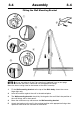
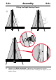
3.5 Assembly 3.5 Fitting the Free Standing Kit (optional) NOTE: The Free standing kit is an optional extra and does not come packed with the main machine. 1. Attach the bracket to the top of the machine using the nuts and screws (provided with the main machine). Extend the telescopic leg to the same length as the front legs less 12cm (5”) Assistance will be needed for the following stages 2. 3. 4.
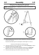
3.61 Assembly 3.61 Fitting the Left Backing Panels 2x 3x 1. 2. 3. 4. Remove the screws and nuts from the edge of the Left small back panel. Fit panel into the groove on the top edge of the Squaring arm, slide the panel to the right and locate the vertical edge into the groove in the Main body. be careful not to damage the edge of the panel. Fit the Left large back panel into the groove on the top edge of the Squaring arm, slide it to the right to meet the small panel.
3.62 Assembly 3.62 Fitting the Right Backing Panels 3x 5. Repeat for the Right hand panels. In place of a vertical groove in the main body the panels have metal strips fixed to the back which grip the edge of the main body as shown.
4.1 Squaring 4.1 Checking your machine for Squareness For your machine to produce accurate square cuts the Main Body needs to be set so that it is 90° to the Squaring Arm, for the following procedure you will need a piece of card or matboard at least 60cm x 100cm (2’ x 3’) the larger the board the more accurate you can set the machine. Place the board on the machine vertically as shown and apply the clamp ensuring the bottom edge is in firm contact with the Squaring Arm.
4.2 Squaring 4.2 Adjusting the Squareness Second cut to the left of previous cut Turn adjustment screw counter clockwise cut to the Second right of previous cut Turn adjustment screw clockwise ➠ ➠ NOTE: Before making any adjustments carry out the squareness check as described on the previous page. It is assumed that the board used for the test is still clamped in the machine.
5.1 Calibration 5.1 Calibrating the Vertical scale 120.5cm (471/ ") 2 120.5cm (471/ ") 2 0 - ZERO NOTE: The Vertical rules can be identified from the Squaring arm rule by the orientation of the printed measurements – see diagram. 1. 2. 3. 4. 5. Trim the bottom scale at zero and 120.5cm (471/2") with scissors. Remove the paper backing tape and carefully place the Rule adjacent to its groove in the Main body and with the zero end resting inside the material channel of the Squaring arm.
5.2 Calibration 5.2 Calibrating the Squaring arm scales ➠ ➠ ➠ NOTE: The Squaring arm rule can be identified from the Vertical rules by the orientation of the printed measurements – see diagram. LEFT HAND SCALE 1. 2. 3. 4. Place a piece of card in the machine and apply the clamp. Mark the top edge of the Squaring arm with a pencil (this can be removed with an eraser later) adjacent to the left hand edge of the board. Cut the board and measure the width of the cut.
5.3 Calibration 5.3 Fitting the Sight-line strip NOTE: A spare Sight-line strip is included with the machine, replacement strips are available from Keencut distributors. ➠ The Sight-line strip is fixed to the clamp and then trimmed by the cutting blade to give an accurate guide when cutting to trim lines, the edge of an image or pencil marks. The clamp simply operates by moving the handle in and out, (more information on operating the clamp is given later). 1.
6.1 Operation 6.1 Using the clamp The Clamping system of the Excalibur has been carefully designed to give a controlled clamping force easily set by the operator to suit the task in hand. The clamp has an integral friction brake that regulates clamping force on the material in relation to the amount of pressure applied to the operating lever. So you can clamp delicate materials very gently or thick PVC Foam Boards rigidly to prevent any movement.
6.2 Operation 6.2 The Multi-tool cutter head & the counterbalance – 5000 The Excalibur 5000 is fitted with two sliding carriages running on a vertical slideway, each carriage being fitted with a cutting head. The top carriage is fitted with a twin wheel cutter for use with rigid particle boards such as MDF, hardboards and some mountboards, refer to ‘Using the twin wheel cutter’ for more details.
6.21 Operation 6.21 Using the Cutting blade ➠ ➠ ➠ ➠ Changing the Cutting blade 1a ➠ 2a Basic Cutting Technique Select the Cutting Blade position on the turret and clamp the material in the machine. Move the cutting head beyond the top of the material to be cut. 1. Press to engage the cutter. Draw the cutter down to the bottom of the machine where it will disengage automatically. 2.
6.22 Operation 6.22 Using the Scoring blade ➠ ➠ Changing the Scoring blade 1b 2b ➠ The scoring blade is designed to score acrylics, plexiglass and other similar rigid plastics. Trials should be carried out on scrap materials first to ensure you obtain the required standard of cut. Scoring/Breaking Technique Select the Scoring Blade position on the turret and clamp the material in the machine. 1. 2. 3. Turn the Rachet Hold-off Knob to disengage the rachet.
6.23 Operation 6.23 Using and changing the Glass cutter ALWAYS WEAR EYE PROTECTION WHEN CUTTING GLASS ➠ Select the Glass cutter position on the turret, place the glass on the machine loading from the right hand side. 1. 2. Apply the clamp lightly and raise the cutting head beyond the top of the glass. Press to engage the cutter fully. The cutting head will automatically adjust itself for the thickness of the glass.
6.3 Operation 6.3 Using the Twin Wheel cutter – 5000 Changing the Twin Wheel cutter 1b 2b The twin wheel cutter is mounted on the upper cutting head and is used for cutting rigid materials such as medium density fibreboard (MDF, also known as SBS) and standard hardboard up to 3mm (1/8”) or harder materials like high density fibreboard (HDF) up to 2mm (1/16”). Many other softer boards and card can also be cut, trials should be carried out to ensure the desired quality of cut is obtained.
7.1 Maintenance 7.1 Cleaning Keencut machines are designed to be virtually maintenance free, however we do recommend regular cleaning. Do not wipe the squaring arm channels or remove any debris with fingers, as it may contain sharp particles such as glass. Use a vacuum cleaner if possible or if a soft brush is used, work slowly and do not allow particles to flick off of the bristles. Lubrication The slideway can be cleaned and lubricated occasionally using a silicone lubricant.