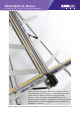
EXCALIBUR 3S Manual PLEASE NOTE THIS IS A TEMPORARY MANUAL Thank you for choosing the Keencut Excalibur 3S. Every effort has been made to bring you a precision engineered product with the promise of many years of valuable service. In order to obtain maximum benefit from your machine please read these instructions carefully. For advice and assistance or replacement parts please contact your distributor or Keencut. Single language versions and parts diagrams can be down loaded from www.keencut.co.
Contents 1 2 Packing List 2.1 Unpacking your machine 3.1 Adjusting the legs 3.2 Preparing to fit the squaring arm 3.3 Fitting the squaring arm 3.4 Fitting the support arms & wall mounting bracket 3.5 Attaching machine to wall with mounting bracket 3.6 Fitting the optional free standing kit 4.1 Checking the machine for squareness 4.2 Adjusting the squareness 5.1 Calibrating the vertical scale 5.2 Calibrating the squaring arm scales 5.
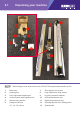
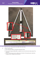
Unpacking your machine 2.1 ❷ ❻ ❼ ❾ ❸ ❶ ❽ ⓬ ❿ ⓫ ⓭ ❹ ❺ NOTE: * When lifting the main body from the box, DO NOT lift using the black handles on the cutters. 1. Main body * 7. Short support arm screws 2. Squaring arm 8. Long support arm fixing screws 3. Left & right hand support arms 9. Leg fixing screws & washers 4. Vertical scale & spare sightline strip 10. Left hand production stop 5. Wall mounting bracket 11. Right hand production stop 6. Hexagon wrenches 12.
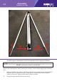
Assembly 3.1 Adjusting the legs ❶ ❷ ❷ ❶ The first stages of assembly are carried out with the machine laying on the floor. NOTE: When lifting the main body from the box do not lift using the black handles on the cutters. DO NOT untie balance weight cord at this stage. Remove the main body from the box and lay it on the floor, remove the packaging from the bottom end. 1.
3.2 Assembly Preparing to fit the squaring arm Ⓐ Ⓒ Ⓑ 1. Move the lower cutting head to the middle of the main body. 2. Remove the following: A. One screw from each leg, using 5mm hexagon wrench. B. Two sets of hexagon headed bolts, washers and nuts from the main body using 17mm spanners. C. Remove small screw and two washers from the back of the squaring arm using 3mm hexagon wrench. (Right hand side ONLY).
3.3 Assembly Fitting the squaring arm ❺ ❹ ❸ ❶ ❷ 1. Slide the squaring arm in from the left hand side through the gap in the main body and align the corresponding screw holes. 2. Fit the two hexagon bolts from the back of the main body, fit the washers and nuts finger tight only. 3. Fit the scews through the squaring arm into the leg using the 5mm hexagon wrench, do not tighten fully. 4.
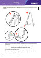
3.4 Assembly Fitting the support arms & wall mounting bracket ❹ ❻ ❸ ❹ ❷ 1. Get help to slowly lift the machine and lean it so the front faces towards the wall. Carefully place a scrap of card or board between the top end of the machine and the wall to prevent any damage. NOTE: Ensure the machine is tied or held in position safely whilst the following steps are carried out. 2. Replace the screw and two washers in the squaring arm using the 3mm hexagon key. 3.
3.5 Assembly Attaching machine to wall with mounting bracket ❷ ❶ ❹ ❸ NOTE A: If you are going to fit the free standing kit (optional) turn to next page. NOTE B: Ensure the wall is stable and use the appropriate fixings. 1. Stand the machine vertical and turn around so the machine is now facing away from the wall. 2. The wall mounting bracket should lay flush against the wall. Mark the position of the wall fixings with a short pencil. 3.
Assembly 3.6 Fitting the optional free standing kit NOTE: The free standing kit is an optional extra and does not come packed with the main machine. ❷ ❶ ❸ 1. Attach the bracket to the top of the machine using the nuts and screws (provided with the main machine). Extend the telescopic leg to the same length as the front legs less 12cm (5”). Assistance will be needed for the following stages 2.
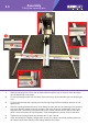
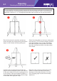
Squaring 4.1 Checking the machine for squareness For your machine to produce accurate square cuts the main body needs to be set so that is is 90o to the squaring arm, for the following procedure you will need a piece of card or mount tboard at least 60cm x 100cm (2’ x 3’). The larger the board the more accurate you can set the machine. ❶ Place the board on the machine vertically as shown and apply the clamp ensuring the bottom edge is in firm contact with the squaring arm.
Squaring 4.2 Adjusting the squareness ❹ Ⓐ Ⓑ Ⓒ Ⓐ NOTE: Before making any adjustments carry out the squareness check as desribed in the previous page. It is assumed that the board used for the test is still clamped in the machine. From the test results determine if the last cut made in the top of the board is to the left or right of the previous cut, as shown above: 1. Slacken the two screws (A) joining the squaring arm to the two legs. 2.
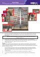
Calibration 5.1 Calibrating the verical scale ❷ ❷ ❸ 1. Trim the bottom of the scale at zero with scissors. 2. Remove the paper backing tape and carefully place the rule adjacent to its groove in the main body and with the zero end resting inside the material channel of the squaring arm. When aligned stick the rule in its groove. 3. Again trim the rule at the bottom end as shown.
5.2 Calibration Calibrating the squaring arm scales ❶ ❷ The top edge of the squaring arm slides left to right to enable calibration. Use the 3mm hexagon wrench to loosen the screw in the back of the squaring arm if adjustment is necessary. 1. Slide the production stop onto the outside edge of the squaring arm as shown. 2. Clamp a piece of card in the machine and move the production stop to it. 3.
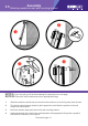
Calibration 5.3 Fitting the sightline strip NOTE: The sightline strip is fitted to your machine but may wear or get marked with use. A spare strip is included with the machine, replacement strips are available from your distributor or Keencut. ❸ ❷ ❹ ❶ The sightline strip is fixed to the clamp and then trimmed using the cutting blade to give an accurate guide when cutting to trim lines, the edge of an image or pencil marks.
6.1 Operation Using the clamp The clamping system enables the operator to control the grip pressure by means of an integral friction brake, that maintains the clamping force at the pressure applied by the operating lever. Soft materials can be held firmly without sustaining damage and solid materials are held rigidly without movement. By following the guidelines below it will help you to get the most from the machine. USE CLAMPING INSTRUCTIONS Soft materials such as Use light to medium pressure.
6.2 Operation The multi-tool cutter head & counterbalance ❸ ❶ ❷ The Excalbur 3S is fitted with two sliding carriages running on a vertical slideway and each carriage is fitted with a cutting head. The top carriage is fitted with a twin wheel cutter for use with rigid boards such as aluminium composite panels, MDF, hardboards. Refer to ‘Using the twin wheel cutter’ for more details.
6.3 ❶ Operation Using & changing the cutting blade ❸ ❺ ❻ ❷ ❹ Basic cutting technique: Select the cutting blade position on the turret and clamp the material in the machine. Move the cutting head beyound the top pf the material to be cut. 1. Press to engage the cutter. Draw the cutter down to the bottom of the machine where it will disengage automatically. 2.
6.4 Operation Cutting thick material using the ratchet latch ❶ ❷ Ratchet latch 1. A unique feature of the Excalibur is the ‘ratchet latch’, this enables thick dense materials such as PVC foam board to be cut easily in stages. Count the number of ‘clicks’ to position the blade just below the surface of the material to make your first cut then add an extra ‘click’ for the second and subsequent cuts. 2. Pull down the latch lever to disengage the ratchet if required.
6.5 Operation Using & changing the scoring blade ❶ ❹ ❸ ❷ ❺ The scoring blade is designed to score acylics, Plexiglas and other similiar rigid plastics. Trials should be carried out on scrap materials first to ensure you obtain the required standard of cut. Scoring/breaking technique Select the scoring blade position on the turret and clamp the material in the machine. 1. Turn the ratchet hold-off knob to disengage the ratchet. 2.
6.6 Operation Using & changing the twin wheel cutter ❷ ❹ ❺ The twin wheel cutter is mounted on the upper cutting head and is used for cutting rigid materials such as aluminimum composite panel and MDF up to 3mm (1/8”). Many other softer boards and card can also be cut, trials should be carried out to ensure the desired quality of cut is obtained.
General maintenance 7.1 ❷ ❶ Ⓐ Ⓐ Ⓑ Ⓐ Ⓐ Cleaning Keencut machines are designed to be virtually maintenance free, however we do recommend regular cleaning. Do not wipe the squaring arm channels or remove any debris with fingers, as it may contain sharp particles such as glass. Use a vacuum cleaner if possible or if a soft brush is used, work slowly and do not allow particles to flick off the bristles. Lubrication The slideway can be cleaned and lubricated occasionally using a silicone lubricant.