MIRACLEAN® GAS GRIDDLE SERVICE MANUAL KEEP THIS MANUAL FOR TRAINING NEW PERSONNEL 1-800-KEATING www.keatingofchicago.
TABLE OF CONTENTS SECTION I INTRODUCTION SECTION V SERVICE DIAGNOSIS Trouble Shooting Chart . . . . . . . . . . . . . . . . . . . . . .8 Safety Precautions . . . . . . . . . . . . . . . . . . . . . . . .1-2 SECTION VI PARTS LIST SECTION II INSTALLATION Ordering Parts . . . . . . . . . . . . . . . . . . . . . . . . . . . . .8 Installation . . . . . . . . . . . . . . . . . . . . . . . . . . . . . . . .2 Warning and Operating Plates . . . . . . . . . . . . . . . .8 Damage During Shipment . . . . . . . . . .
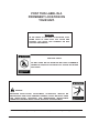
POST THIS LABEL IN A PROMINENT LOCATION ON YOUR UNIT. IMPORTANT IN THE EVENT A GAS ODOR IS DETECTED, SHUT DOWN UNITS AT MAIN SHUT OFF VALVE AND CONTACT THE LOCAL GAS COMPANY OR GAS SUPPLIER FOR SERVICE. FOR YOUR SAFETY DO NOT STORE OR USE GASOLINE OR OTHER FLAMMABLE VAPORS OR LIQUIDS IN THE VICINITY OF THIS OR ANY OTHER APPLIANCE. WARNING IMPROPER INSTALLATION, ADJUSTMENT, ALTERATION, SERVICE OR MAINTENANCE CAN CAUSE PROPERTY DAMAGE, INJURY OR DEATH.
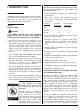
IMPORTANT: In the event a gas odor is detected, shut down unit at main shut-off valve and contact the local gas company or gas supplier for emergency service. I INTRODUCTION You must maintain this appliance free and clear from MODEL VARIATIONS combustibles. Standard Griddles: Keating MIRACLEAN gas griddles are available in sizes ranging from 27" to 72" and in depths 24", 30", 33" and 36". The gas griddles are AGA, CSA, and NSF design certified.
operated and maintained as follows: II INSTALLATION Installed in accordance with all local codes, or in the absence of local codes, with the current National Fuel Gas Code Z223.1 (latest edition). National Gas Installation CAN/CGA-B149.1, or the Propane Installation Code, CAN/CGA-B149.2.
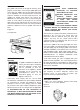
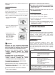
LEVELING GAS CONNECTION PIPE The griddle will operate at its highest efficiency when properly leveled. Place a level on the griddle plate from side to side. For griddles on legs, the bottom foot of the leg is adjustable. Turn counterclockwise to decrease height or clockwise to increase height until level. For griddles on stands with casters, the casters are adjustable by loosening the jam nut and turning the caster in or out. When the desired level is reached, tighten the jam nut.
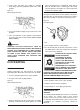
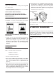
2. Close main and pilot gas supply by partially depressing and turning ON/OFF knob to the “OFF” position. panel until pilot flame is established. Allow pilot to burn 90 seconds before releasing gas valve knob. This will allow the thermopile to reach its maximum millivolt and milliamp output. Figure 2-3 NOTE: Allow pilot to burn one additional minute before turning thermostat dial to desired position.
1. Follow cleaning instruction on page 7. 4. Load the product to the left and right of each inverted “V” first, then fill the area above the thermostat sensing bulb. See figure 3-3. 2. Heat the MIRACLEAN® to 400°F for one hour. 3. Lower thermostat to 350°F, allowing the MIRACLEAN® to cool to about 350°F, as is evident when griddle cycles on or surface thermometer indicates correct temperature.
USE ONLY A KEATING STEEL SPATULA. NOTE: Damage done to the MIRACLEAN® surface is irreparable. DO NOT CLEAN SCRAPER ON SPLASHBACK, GREASE BUILD-UP WILL OCCUR WHICH MAY RESULT IN A FIRE. CLEANING THE GRIDDLE DO NOT STORE ANYTHING IN OR ON THE FLUE The surface of the MIRACLEAN® Griddle is very durable and with proper care, following the procedures below, will last many years. OF THE MIRACLEAN®.
4. When burners cycle off, griddle is up to temperature. If temperature is within 25°F of thermostat setting, loosen the four retaining screws on the dial plate. Rotate the dial plate. Indicating arrow on the thermostat knob should point to the temperature indicated on the thermometer. CLEANING Proper care should be taken to fully clean the griddle on a regular basis. A. CONTROL PANEL – Clean any grease build-up on switches and thermostat knobs.
TROUBLE SHOOTING CHART PROBLEM PROBABLE CAUSE No pilot SOLUTION c. Quick disconnect not tight. d. Gas valve is in “OFF” position. e. Faulty Piezo Ignitor. a. Open gas supply valve. b. Press gas valve knob in “pilot” position and hold. c. Tighten quick disconnect. d. Turn valve knob to “pilot”. e. Replace ignitor. Pilot won’t stay on a. Loose thermopile. b. Faulty thermopile. a. Tighten fitting and/or terminal leads. b. Replace thermopile. Pilot on but no main burner ignition a.
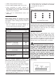
5 6 THERMOSTAT KNOB 400° 004163 THERMOSTAT KNOB 550° 002615 PIEZO SPARK IGNITOR ASSEMBLY A. MOUNTED ON LEFT, 45° BRACKET. USED ON ALLNATURAL GAS STANDARD GRIDDLES AS WELL AS 27” AND 30” LEFT SIDE ON SINGLE BURNER PROPANE GRIDDLES. 010946 B. MOUNTED ON RIGHT. 45° BRACKET. USED ON BEF 36” & 27: AND 30” RIGHT SIDE GRIDDLES.
SECTION VII WIRING DIAGRAM GAS GRIDDLE WIRING DIAGRAM 10
WARRANTY OF OTHER TERMS AND CONDITIONS KEATING OF CHICAGO, INC., 1-800-KEATING, WWW.KEATINGOFCHICAGO.COM KEATING REFILE/warranty 3/09 TO SECURE WARRANTY SERVICE All repair services under this Limited Warranty must be authorized by Keating or performed at Keating. Authorization may be obtained by calling 1-800-KEATING within the Continental United States, Alaska, Hawaii, Puerto Rico and Canada during normal business hours (8 a.m. through 5 p.m. Central Time, Monday through Friday).
SERVICE INFORMATION If you have a service related question call 1-800-KEATING. Please state the nature of the call; it will ensure speaking with the appropriate person. Have your serial and model number available when ordering parts. KEATING OF CHICAGO, INC. Phone: (708) 246-3000 FAX: (708) 246-3100 Toll Free 1-800-KEATING (In U.S. and Canada) www.keatingofchicago.com *As continuous product improvement occurs, specifications may be changed without notice.