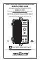
INSTALLATION AND OPERATING INSTRUCTIONS MODEL KBRC-240D FULL-WAVE 4-QUADRANT REGENERATIVE DRIVE NEMA 4X, IP-65 KB Part No. 8840 (Black Case) • Part No.
TABLE OF CONTENTS Section Page i. Simplified Operating Instructions . . . . . . . . . . . . . . . . . . . . . . . . . . . . . . . . . . . . . . . . . . . . . 4 ii. Safety Warning . . . . . . . . . . . . . . . . . . . . . . . . . . . . . . . . . . . . . . . . . . . . . . . . . . . . . . . . . . 5 I. Introduction . . . . . . . . . . . . . . . . . . . . . . . . . . . . . . . . . . . . . . . . . . . . . . . . . . . . . . . . . . . . . 5 II. Wiring Instructions . . . . . . . . . . . . . . . . . . . . .
15. DC Tach-Generator Connection . . . . . . . . . . . . . . . . . . . . . . . . . . . . . . . . . . . . . . . . . . . . 14 16. DC Tach-Generator Connection with Addition of RT . . . . . . . . . . . . . . . . . . . . . . . . . . . . . 14 17. AC Line Input Voltage Selection (J1 and J2) . . . . . . . . . . . . . . . . . . . . . . . . . . . . . . . . . . 14 18. Motor Voltage Selection (J3) . . . . . . . . . . . . . . . . . . . . . . . . . . . . . . . . . . . . . . . . . . . . . . . 14 19.
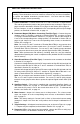
i. SIMPLIFIED OPERATING INSTRUCTIONS IMPORTANT – You must read these simplified operating instructions before proceeding. These instructions are to be used as a reference only and are not intended to replace the detailed instructions provided herein. You must read the Safety Warning, on page 5, before proceeding. A.
ii. ! SAFETY WARNING! Please read carefully This product should be installed and serviced by a qualified technician, electrician, or electrical maintenance person familiar with its operation and the hazards involved.
Potentiometer rotation or input signal. In the Non-Linear Torque mode (NL), the torque is varied by the Main Speed Potentiometer or input signal, and remains constant throughout the motor’s entire speed range. In addition, Regenerate-to-Stop (RTS) or Coast-to-Stop (CTS) stop modes are also provided. Standard front panel features of the KBRC-240D include diagnostic LEDs (for Power On, Stop and Overload), a Start/Stop Switch and a Main Speed Potentiometer.
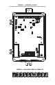
FIGURE 1 – CONTROL LAYOUT (Illustrates Factory Setting of Jumpers and Approximate Trimpot Settings) OFFSET RACC FACC IR RESP DB TCL T- TB3 J10 ON NO NC J5 G R B TCL J8 NTCL TRQ SPD J6 1.7A 2.5A 5A 7.
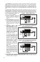
8.226 [208.94] 8.876 [225.45] 9.488 [241.00] 0.357 [9.07] STOP OL FWD TM MANUAL STOP TM KBRC-240D SHOWN WITH OPTIONAL FORWARD-BRAKE-REVERSE AND AUTO/MANUAL SWITCHES AUTO 100 START NEMA-4X / IP-65 REV % 10 0 80 90 20 60 70 50 30 40 REGENERATIVE DC MOTOR SPEED CONTROL PENTA-DRIVE 5.000 [127.00] 5.472 [138.99] ON RECOMMENDED MOUNTING SCREW: 1/4" (M6) 5.886 [149.
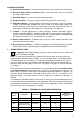
STANDARD FEATURES A. Short Circuit Protection – Protects the control from a short circuit at motor connections. B. Electronic Motor Burnout Protection (I X t) – Shuts down the control if a prolonged overload condition exists. C. Start/Stop Switch – Provides electronic start/stop function. D. Diagnostic LEDs – For power on (ON), stop (STOP) and motor overload (OL). E.
Warning! Do not wire switches or relays in series with the armature. Armature switching can cause catastrophic failure of motor and/or control. To avoid erratic operation, do not bundle AC line and motor wires with potentiometer wires, voltage following wires, Start/Stop Switch wires, enable wires, or any other signal wires. Use shielded cables on all signal wiring over 12” (30cm) long. The shield should be earth grounded on the control side only.
Note: Do not connect motor armature leads to F1 and F2 quick-connect terminals. Do not use F+ and F- terminals of Terminal Block TB2 for any purpose other than to power the field of a shunt wound motor. E. Half Voltage Field Connection (Shunt Wound Motors Only) – Wire the motor field leads to F+ terminal of Terminal Block TB2 and L1 terminal of Terminal Block TB1, as shown in Figure 6, on page 10 and as described in Table 4.
COM +15V -15V SIG FIGURE 9 – BIDIRECTIONAL MAIN SPEED 3. Bidirectional Operation – POTENTIOMETER CONNECTION Provides forward and reverse operation using the Main Speed LOW (WHITE) Potentiometer. Connect the WIPER (ORANGE) Main Speed Potentiometer high HIGH (VIOLET) side to +15V terminal, wiper to SIG terminal and low side to MAIN SPEED -15V terminal, as shown in POTENTIOMETER (BACK VIEW) Figure 9. Zero motor speed will now be located at 50% rotation.
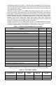
H. Run Relay Connection – Normally TABLE 5 – RUN RELAY OUTPUT CONTACTS open (NO) or normally closed (NC) JUMPER J10 RUN RELAY MODE POSITION CONTACTS relay output contacts are available at Terminal Block TB3, which change NO Closed Run state when the Start/Stop Switch is NC Open set to the “START” position.
the motor armature voltage. If the tach-generator polarity is reversed, the motor will accelerate to full speed and the Main Speed Potentiometer will not control speed. Tachgenerator feedback can greatly improve speed regulation and dynamic response. Note: When using a tach-generator, the IR trimpot should be set fully counterclockwise. Note: The tach-generator input is designed for 7 Volt or 50 Volt per 1000 RPM tach-generators used with 1800 RPM motors.
Note: If Jumper J3 is set to the “T7” or “T50” position, a tach-generator must be wired to Terminal Block TB3. If a tach- generator is not used, Jumper J3 must be in either the “A180” or “A90” position. If jumper J3 is in the “T7” or “T50” position, and a tach-generator is not used, the motor will accelerate to full speed and the Main Speed Potentiometer will not control speed. C. DC Tach-Generator Voltage Selection (J3) – Jumper J3 is factory set to the “A180” position for 180 Volt motors.
F. Control Mode Selection (J6) – Jumper J6 is factory set to the “SPD” position for Speed Control Mode . For Torque Control Mode, set Jumper J6 to the “TRQ” position. See Figure 22. FIGURE 22 – CONTROL MODE SELECTION J6 Set for Speed Control Mode (Factory Setting) J6 Set for Torque Control Mode TRQ SPD TRQ SPD G. Torque Control Mode Selection (J7) – J6 J6 Jumper J7 is factory set to the “S/L” position for Speed Mode and Linear Torque Mode.
FIGURE 27 – ENABLE JUMPER K. Enable Jumper (J11) – Jumper J11 is factory installed to enable the control. If installing the Enable Circuit, as described in Section IIJ, on page 13, remove Jumper J11. See Figure 27. J11 Installed for Auto-Enable (Factory Setting) EN J11 Not installed for Manual Enable EN J11 J11 IV. MOUNTING INSTRUCTIONS ! Warning! The KBRC-240D is not designed to be used in an explosion-proof application.
C. The hi-pot test voltage should be set in accordance to the testing agency standards and the leakage current should be set as low as possible without causing nuisance trips. D. To eliminate motor speed control damage due to auxiliary equipment hi-pot failure, it is also recommended that all signal inputs be wired together and connected to the AC input lines as shown. VI.
FIGURE 31 – OFFSET TRIMPOT RANGE VIII. TRIMPOT ADJUSTMENTS The KBRC-240D contains trimpots which are factory set for most applications. Figure 2, on page 7, illustrates the location of the trimpots and their approximate calibrated positions. Some applications may require readjustment of the trimpots in order to tailor the control for a specific requirement. Readjust trimpots as described below.
output (RACC also sets the forward deceleration time). To increase the reverse acceleration time, rotate the RACC trimpot clockwise. To decrease the reverse acceleration time, rotate the RACC trimpot counterclockwise. C. Maximum Speed (MAX) – Sets maximum speed of the motor. The MAX trimpot is factory set for 100% of base motor speed. For a higher maximum speed setting, rotate the MAX trimpot clockwise. For a lower maximum speed setting, rotate the MAX trimpot counterclockwise. See Figure 36.
Note: If the IR compensation is too high, unstable (oscillatory) operation will result. If the control is used with a DC tach-generator, the IR trimpot should be set fully counterclockwise. To Calibrate the IR Trimpot: 1. Run the motor at approximately 30 - 50% of rated speed at no load and measure the actual speed. 2. Load the motor to the rated current. Adjust the IR trimpot so that the loaded speed is the same as the unloaded speed measured in step 1. FIGURE 40 – RESP TRIMPOT RANGE F.
To reset the control after it has gone into TCL , momentarily set the Start/Stop switch to the “START” position or disconnect and reconnect the AC line. See Figure 43, on page 21. Resetting the Control after TCL – To reset the control after it has gone into TCL, set the Start/Stop switch to the “STOP” position and then momentarily to the “START” position or disconnect and reconnect the AC line.
A. Forward-Stop-Reverse Switch (P/N 9485) – Provides motor reversing and regenerative braking. Mounts on the enclosure cover and is supplied with a switch seal to maintain watertight integrity. B. Power On/Off Switch (P/N 9486) – Disconnects the AC line. Mounts on the enclosure cover and is supplied with a switch seal to maintain watertight integrity. C. Signal Isolator SIRC (P/N 8842) – Provides isolation between a non-isolated signal voltage source and the KBRC-240D.
XI. LIMITED WARRANTY For a period of 18 months from the date of original purchase, KB Electronics, Inc. will repair or replace, without charge, devices which our examination proves to be defective in material or workmanship. This warranty is valid if the unit has not been tampered with by unauthorized persons, misused, abused, or improperly installed and has been used in accordance with the instructions and/or ratings supplied.