
User Guide
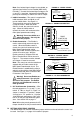

E. Run Relay Output Mode Selection (J5)
– Jumper J5 is factory set to “NO” position
for normally open relay output at TB4. For
normally closed relay output, set jumper
J5 to “NC” position. See Figure 20.
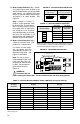
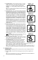
F. Stop Switch Type Selection (J6) –
Jumper J6 is factory set to the “NO” position
for a normally open stop switch, as used on
the front cover. If a remote normally closed
stop switch is used, set Jumper J6 to the
“NC” position. If a remote normally open
stop switch is used, set Jumper J6 to the
“NO” position. See Figure 21.
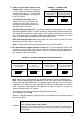
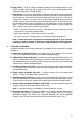
G. Enable Selection (J7) – Jumper J7 is fac-
tory installed to enable the control. If con-
necting Enable contacts to Terminals EN1
and EN2 of Terminal Block TB3, remove
Jumper J7. See Figure 22.
V. MOUNTING INSTRUCTIONS
Warning! The KBPW-240D is not
designed to be used in an explo-
sion-proof application.
It is recommended that the control be mount-
ed vertically on a flat surface with adequate
ventilation. Leave enough room below the
control to allow for AC line, motor connec-
tions, and any other wiring. Although the
control is designed for outdoor and wash-
down use, care should be taken to avoid
extreme hazardous locations where physi-
cal damage can occur. If the control is
mounted in a closed, unventilated location,
allow enough room for proper heat dissipa-
tion. If operating the control at full rating, a
minimum enclosure size of 12”W x 24”H x
12”D is required. See Figure 2, on page 5.
The KBPW-240D is designed with a hinged
case so that when the front cover is open,
all wiring stays intact. To open the cover, the four
screws must be loosened so they are no longer
engaged in the case bottom. After mounting and
wiring, close the cover and make sure that wires will
not get caught or crimped as the cover is closed.
Tighten all four cover screws so that the gasket is
slightly compressed.
Do not over tighten.
VI. OPERATION
Caution!
It is recommended that the bus capacitors
be reconditioned if this product has been in storage for over one year. To recondition the capac-
itors, apply the AC line, with the drive in Stop Mode, for a minimum of one hour.
After the control has been properly set up (jumpers set to desired positions and wiring com-
pleted), the startup procedure can begin. If AC power has been properly brought to the con-
trol, the ON and STOP LEDs will be illuminated. Before starting, be sure the main speed
12
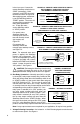
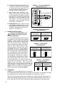
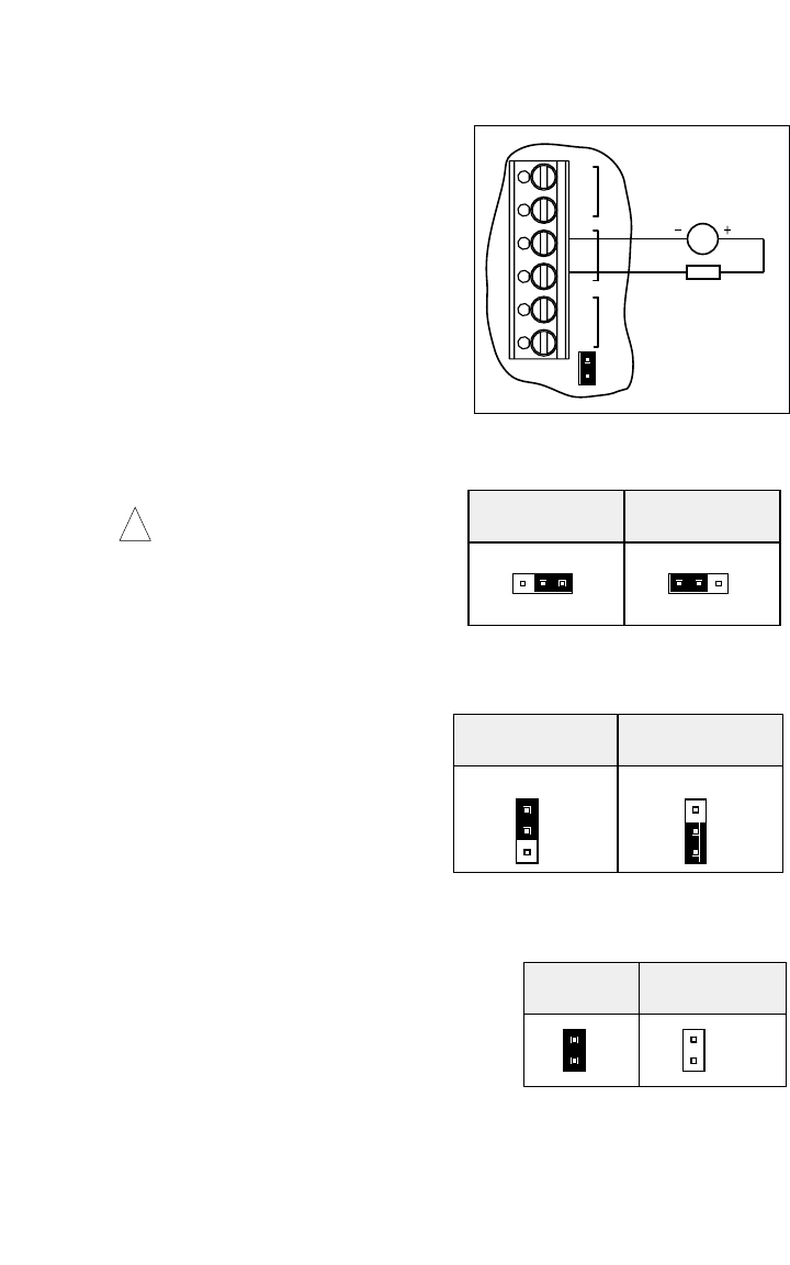
ENABLEEN
J7
DC TACH-GENERATOR
RT
EN1
EN2
T-
T+
TACH
K2
RELAY
K1
TB3
G
FIGURE 19 – DC TACH-GENERATOR
WITH ADDITION OF RT
!
J5 Set for Normally Open
(NO) Output Contacts
(Factory Setting)
J5 Set for Normally Closed
(NC) Output Contacts
NC NO
J5
J5
NONC
FIGURE 20 – RUN RELAY OUTPUT
MODE SELECTION
J6 Set for
Normally Open Stop Switch
(Factory Setting)
J6 Set for
Normally Closed Stop Switch
STOP
NO
NC
J6
STOP
NO
NC
J6
FIGURE 21 – STOP SWITCH
TYPE SELECTION
J7 Installed to
Enable the Control
(Factory Setting)
J7 Removed to
Connect Enable Contacts
EN
J7
EN
J7
FIGURE 22 – STOP SWITCH
TYPE SELECTION