
User Guide

11
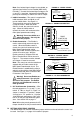
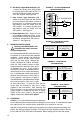
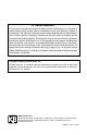
C. Timed and Non-Timed Current Limit
Selection (J3) – Jumper J3 is factory set
to “TCL” position for timed current limiting
operation. See Figure 17. For non-timed
current limiting operation, set jumper J3
to “NTCL” position.
TCL (Timed Current Limit) – When
Jumper J3 is in the “TCL” position, the
control will go into “STOP” after it is in
overload for a predetermined amount of
time (set by the TCL trimpot).
Resetting the Control After TCL – To reset the control after it has gone into TCL, momen-
tarily set the Start/Stop switch to “START” position or disconnect and reconnect the AC line.
If an On/Off AC Line Switch is installed, set it to “OFF” position and then back to “ON” posi-
tion. If the Start switch is jumpered (START and COM terminals connected), the control
must be restarted by disconnecting and reconnecting the AC line.
NTCL (Non-Timed Current Limit) – When jumper J3 is set to “NTCL” position, the control
will not go into “STOP” after it is in overload.
Note: TCL trimpot will have no affect when jumper J3 is in “NTCL” position.
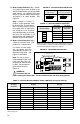
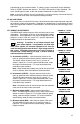
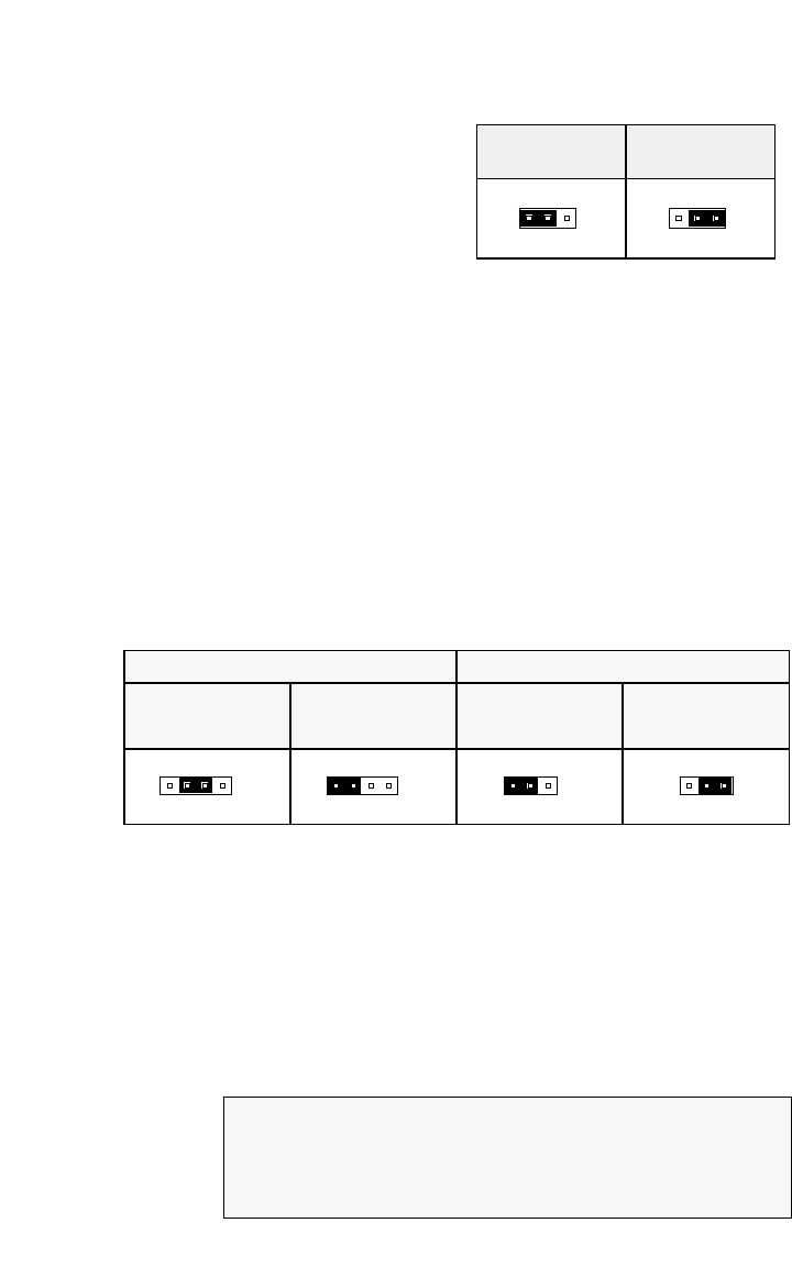
D. DC Tach-Generator Voltage Selection (J1 and J4) – For a tach-generator wired to TB3,
set jumper J1 to “T” position. See Figure 18. Jumper J4 is factory set to “7V” position for 7
Volt per 1000 RPM tach-generators wired to TB3. For a 50 Volt per 1000 RPM tach-gener-
ator, set jumper J4 to “50V” position.
Note: When using a tach-generator, the IR trimpot should be set fully counterclockwise.
Note: The tach-generator input is designed for 7 Volt or 50 Volt per 1000 RPM tach-gen-
erators used with 1800 RPM motors. For tach-generators other than 7 Volt or 50 Volt per
1000 RPM or for motors other than 1800 RPM, an external 1/2 watt resistor (RT) must be
used. Install R
T in series with the tach-generator as shown in Figure 19, on page 12.
Jumper J4 must be set to “7V” position.
The value of RT in Ω can be calculated using the following formula:
RT = (1.46 x VT x S) - 19,000
Where VT is the tach-generator voltage (in Volts per 1000 RPM) and S is the base speed of
the motor (in RPM).
J3 Set for TCL Mode
(Timed Current Limit)
(Factory Setting)
J3 Set for NTCL Mode
(Non-Timed Current Limit)
TCL NTCL
J3
J3
NTCLTCL
FIGURE 17 – CURRENT LIMIT
MODE SELECTION
50V
7V7V
50V
90V
180V
T
J1
J4 J4
90V
J1
180V
T
J1 Set for 90 Volt Motors
(Factory Setting)
J4 Set for 7V per 1000RPM
Tach-Generator Input
(Factory Setting)
J4 Set for 50V per 1000RPM
Tach-Generator Input
J1 Set for
Tach-Generator Input
Jumper J1 Settings Jumper J4 Settings
FIGURE 18 – DC TACH-GENERATOR VOLTAGE SELECTION
Suppose you have a 20 Volt per 1000 RPM tach-generator with a 3600 RPM motor:
RT = (1.46 X 20 X 3600) - 19000 = 86120Ω.
Choose the closest 1/2W resistor value, which is 82000Ω (82kΩ) or 91000Ω (91kΩ).
Readjustment of the MAX trimpot may be necessary to achieve the desired maximum
output voltage.
Example: