
User Guide

Note: If an isolated signal voltage is not available, an
optional signal isolator can be installed (KBSI-240D,
P/N 9431). Connect the isolated signal voltage to P2
(+) and P1 (-) terminals. Adjustment of the MIN trim-
pot may be necessary to achieve a 0 Volt DC output.
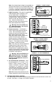
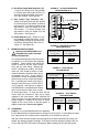
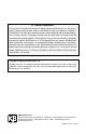
J. Inhibit Connection – The control is supplied with
inhibit terminals (INH1 and INH2) to con-
nect an Inhibit switch. See Figure 10.
These terminals are used to electronical-
ly stop the control. When the Inhibit
switch is closed, the control will coast to
stop. When the Inhibit switch is
opened, the control will accelerate to the
main speed potentiometer setting.
Warning! Do not use Inhibit as a
safety disconnect. Use only the
AC line for this purpose.
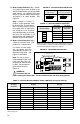
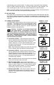
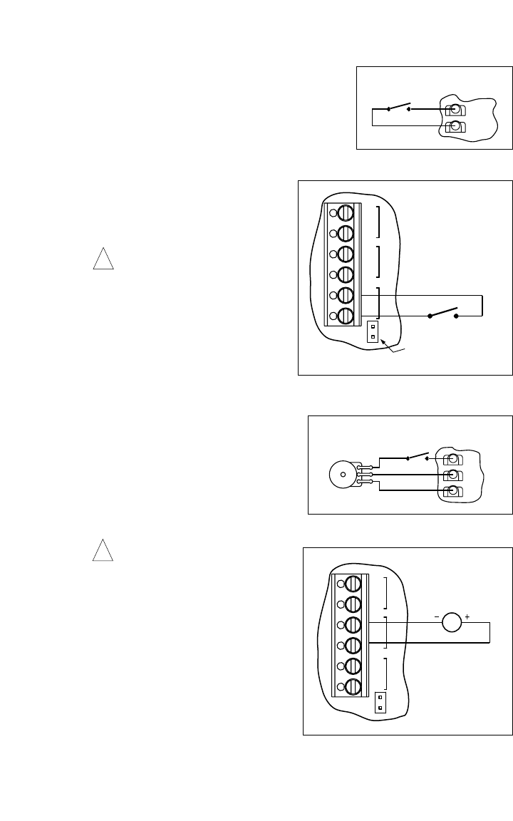
K. Enable Connection –
The Enable is
used to electronically start and stop the
control. When the Enable contact is
closed, the control will accelerate to the
Main Speed Potentiometer setting.
When the Enable contact is opened, the
control will coast to stop. Wire the
Enable contacts to Terminals EN1 and
EN2 of Terminal Block TB3 as shown in
Figure 11. The contacts must be isolated
and Jumper J7 must be removed.
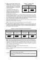
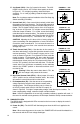
Note: The control can also be started and
stopped with an Enable contact in the
Main Speed Potentiometer circuit. The
Enable function is established by wiring a
switch in series with the violet Main Speed
Potentiometer lead which connects to the
P3 terminal. See Figure 12.
Warning! Do not use Enable as a
safety disconnect. Use only the
AC line for this purpose. The Enable
Circuit is not isolated and is not to be
Earth grounded.
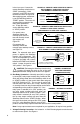
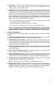
L. DC Tach-Generator Connection –
Wire
the tach-generator to T+ (+) and T- (-) ter-
minals of TB4 as shown in Figure 13.
Jumper J1 must be in “T” position. Jumper
J4 must be in “7V” position for 7 Volt per
1000 RPM tach-generators or “50V” posi-
tion for 50 Volt per 1000 RPM tach-gener-
ators. See section IVD on page 11.
Note: When using a tach-generator, the IR
trimpot should be set fully counterclockwise.
IV. SETTING SELECTABLE JUMPERS
The KBPW-240D has customer selectable jumpers which must be set before the control can
be used. See Figure 1, on page 4 for location of jumpers.
9
(CLOSE TO STOP)
(OPEN TO RUN)
INHIBIT
INH2
INH1
FIGURE 10 – INHIBIT CIRCUIT
!
(CLOSE TO RUN)
(OPEN TO STOP)
ENABLE
Orange
White
Violet
Potentiometer
Main Speed
P3
P2
P1
FIGURE 12 – ENABLE CIRCUIT
USING POTENTIOMETER
!
ENABLEEN
J7
DC TACH-GENERATOR
EN1
EN2
T-
T+
TACH
K2
RELAY
K1
TB3
G
FIGURE 13 – DC TACH-GENERATOR
ENABLEEN
J7
ENABLE
Note: Jumper J7 must be
removed for Enable to operate.
(CLOSE TO RUN)
(OPEN TO STOP)
EN1
EN2
T-
T+
TACH
K2
RELAY
K1
TB3
FIGURE 11 – ENABLE CONNECTION