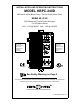
INSTALLATION AND OPERATING INSTRUCTIONS MODEL KBPC-240D KB Part No. 9338 (Black Case) • Part No. 9342 (White Case) NEMA 4X, IP-65 SCR Speed and Torque Control Designed For DC Motors Rated 1/50 – 1 HP @ 90VDC, 1/25 – 2 HP @ 180VDC TM This control will not operate without installing the correct armature fuse – supplied separately. Note: Product illustration is shown with optional ForwardBrake-Reverse and Run-Jog options.
TABLE OF CONTENTS Section Page i. KBPC-240D Simplified Operating Instructions . . . . . . . . . . . . . . . . . . . . . . . . . . . . . . . . . . 1 ii. Safety Warning . . . . . . . . . . . . . . . . . . . . . . . . . . . . . . . . . . . . . . . . . . . . . . . . . . . . . . . . . 2 I. General Information . . . . . . . . . . . . . . . . . . . . . . . . . . . . . . . . . . . . . . . . . . . . . . . . . . . . . 2 II. Setting Selectable Jumpers . . . . . . . . . . . . . . . . . . . . . . . . . . . . . . . . . .
i. KBPC-240D SIMPLIFIED OPERATING INSTRUCTIONS IMPORTANT – You must read these simplified operating instructions before you proceed. These instructions are to be used as a reference only and are not intended to replace the detailed instructions provided herein. You must read the Safety Warning on page 2 before proceeding. 1. CONNECTIONS. A. AC Line – Wire AC line voltage to terminals L1 and L2. Be sure jumpers J2A and J2B are both set to the correct input line voltage 115 or 230 VAC.
ii. SAFETY WARNING! — PLEASE READ CAREFULLY This product should be installed and serviced by a qualified technician, electrician or electrical maintenance person familiar with its operation and the hazards involved.
FIG.
4 TM TM FIG.
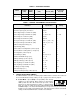
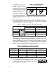
TABLE 1 – ELECTRICAL RATINGS Model KBPC-240D Input Voltage (VAC) Max. AC Current (ARMS) Output Voltage (VDC) Max. DC Output Current (ADC) Max. Horsepower HP, (KW) 115 15.0 0 – 90 10.2 1, (.75) 230 15.0 0 – 180 10.2 2, (1.5) 230 15.0 0 – 90 10.2 1, (.
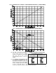
FIG. 3 – MOTOR SPEED vs POTENTIOMETER ROTATION – [SPEED MODE] FIG. 4 – PRESET MOTOR SPEED vs MOTOR LOAD – [SPEED MODE] When Jumper J1 is placed in the "TRQ" position, the drive will control motor torque as a linear function of main potentiometer rotation. If the motor load exceeds the torque setting, the motor will stall, the Overload LED will light, and the drive will apply a constant preset torque based on the potentiometer setting.
FIG. 5 – MOTOR OUTPUT TORQUE vs POTENTIOMETER ROTATION – [TORQUE MODE] FIG. 6 – MOTOR SPEED vs APPLIED MOTOR LOAD – [TORQUE MODE] B. J2A, J2B – Input AC Line Voltage – Select proper input line voltage 115VAC or 230VAC by placing both J2A and J2B in the correct corresponding positions, "115V" or “230V.” TABLE 3 – SETTING AC LINE VOLTAGE WITH JUMPER J2A and J2B Control Set for 230 VAC (Factory Setting) Control Set for 115 VAC C.
For 230VAC line input, the armature voltage is normally set to"180V". However, it is also possible to operate in a StepDown Mode (90 – 130VDC motor with a 230VAC line) by setting J3 to "90". However, reduced performance may result. TABLE 4 – SETTING ARMATURE VOLTAGE WITH JUMPER J3 Control Set for 180 VDC (Factory Setting) Control Set for 90 VDC If tach-generator feedback is to be used, J3 must be placed in the "T" position and an external DC tachgenerator must be connected. See section II, F, p.
1. Timed current limit "TCL": In this mode the drive will turn off after being in current limit for a preset time. The time period is adjustable with the TCL trimpot from 0.5-15 seconds and is factory set for approximately seven (7) seconds. TCL provides electronic motor overload protection. Application Note: After the control times out in TCL, it can be reset using the Start Switch by setting the switch to the "STOP" position and then to "START," or by disconnecting and reconnecting the AC line.
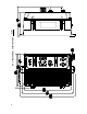
FIG. 7A – CAPTIVE SCREW TIGHTENED IN CASE IV. WIRING. FIG. 7B – CAPTIVE SCREW ENGAGED IN FRONT COVER Warning! Read Safety Warning before attempting to use this control. Warning! To avoid erratic operation do not bundle AC Line and motor wires with potentiometer, voltage following, enable, inhibit or other signal wiring. Use shielded cables on all signal wiring over 12" (30 cm) – Do not ground shield. Wire control in accordance with the National Electric Code requirements, and other codes that apply.
TABLE 8 – RELATIONSHIP of AC LINE INPUT AND MOTOR VOLTAGE with J2 and J3 JUMPER POSITION AC INPUT VOLTAGE J2A, J2B POSITION J4 POSITION MOTOR VOLTAGE 115 115 90 90 230 230 180 180 230 230 90* 90* *A 90VDC motor can be used with a 230VAC line. However, speed range may be reduced and motor derating may be required. C. Field – For Shunt Wound Motors Only. Do not use terminals F1 and F2 for any other purpose than to power the field on a shunt wound motor.
Note: If the tach voltage is connected backwards, the control will drive the motor at full speed only. Note: If the Forward-Brake-Reverse switch is used, provision must be made to reverse the polarity of the tach-generator leads when the control is switched to "Reverse." Warning! To avoid erratic operation do not bundle AC Line and motor wires with potentiometer, voltage following, enable, inhibit or other signal wiring. Use shielded cables on all signal wiring over 12" (30 cm) – Do not ground shield. F.
FIG. 15 – ENABLE CIRCUIT V. FUSING. A. AC Line Fusing – Most electrical codes require that each ungrounded conductor contain fusing. Separate branch circuit fusing, or circuit breaker may be required. Check all electrical codes that may apply to the installation. This control does not contain AC line fuses. A 20 amp rated fuse or circuit breaker can be used. B. Armature Fusing – The correct size armature fuse must be installed, depending on the rating of the motor.
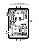
VII. TRIMPOT ADJUSTMENTS. The control contains trimpots, which have been factory adjusted for most applications. Figure 1 page 3 illustrates the location of the trimpots and their approximate adjustment positions. Some applications may require readjustment of the trimpots in order to tailor the control to exact requirements. (See table 2, p. 5 for range and factory setting of all trimpots.) Readjust trimpots as follows: WARNING. Do not adjust trimpots with main power on if possible.
2. Do not leave the motor in a locked condition for more than a few seconds since armature damage may occur. F. IR Compensation (IR) – The IR comp circuit is used to stabilize motor speed under varying loads. (Note: If control is in Tach Feedback mode, the IR trimpot should be set to minimum - ccw.) Readjust the IR trimpot as follows: 1. Run the motor at approximately 30-50% of rated speed under no load and measure actual speed; 2. Load the motor to rated current.
C. Signal Isolator (Model KBSI-240D, P/N 9431) – Signal isolation is required when a remote nonisolated analog signal is to be used. Provision is made to install Model KBSI240D on 4 bosses inside the front cover. The unit accepts a variety of voltage and current signals. Note: Foward-Brake-Reverse Switch (P/N 9339) cannot be installed with Signal Isolator. D. Auto/Manual Installation Kit (P/N 9377) – This kit facilitates mounting of KBSI-240D Signal Isolator into KBPC-240D.
20 FIG.
21 FIG. 18 – INTERNAL CONNECTION DIAGRAM APRM®-PC (Electronic FWD-BRK-REV) FIG.
X – LIMITED WARRANTY For a period of 18 months from date of original purchase, KB will repair or replace without charge devices which our examination proves to be defective in material or workmanship. This warranty is valid if the unit has not been tampered with by unauthorized persons, misused, abused, or improperly installed and has been used in accordance with the instructions and/or ratings supplied.