
Installation Manual


31
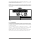
FIGURE 20
ANALOG INPUT JUMPER J2 SETTINGS
8.4.2.1.1 VOLTAGE FOLLOWING
Connect the 0 – ±5 or 0 – ±10 Volt DC Voltage Signal input to TB1 Terminal "3" and the
common to TB1 Terminal "4". Set Jumper J2 to the corresponding signal input voltage (factory
set to "5V" position). Connect the Start (Jumper) to TB1 Terminal "9", which is factory set for
N.O. Start ("0010") and to either common TB1 Terminal "4" or "11" Set the signal Slope and
Type and adjust the Gain, Offset, and Response Time as desired. See Figure 21, for
connections, Jumper J2 settings, and drive programming.
FIGURE 21
VOLTAGE FOLLOWING
CONNECTIONS, JUMPER J2 SETTINGS, AND DRIVE PROGRAMMING
*Factory setting.
MEMORY
MODULE
Jumper J2 Settings
+
Program Function Setting
1.00: Run/Stop-Forward/Reverse Control 0001: External Contacts*
2.01: Remote Frequency Control 0000: Analog Signal 1*
7.04: Multi-Function Input 5 (TB1 Term. 9) 0010: N.O. Start (2-Wire or 3-Wire Start/Stop)*
9.00: Analog Input 1 Gain (%) 0 – 500% (100%*)
9.01: Analog Input 1 Slope
0000: Positive*
0001: Negative
9.02: Analog Input 1 Offset (%) 0 – 100% (0%*)
9.03: Analog Input 1 Type
0000: Unidirectional*
0001: Bidirectional
0002: PWM
9.04: Analog Input 1 Response Time (mSec) 2 – 100 mSec (2 mSec*)