INSTALLATION AND OPERATION MANUAL KBDF SERIES DIGITAL AC DRIVE IP-20 Enclosure Rated for 208 – 230 and 400/460 Volt 50 & 60 Hz 1/8 HP thru 5 HP 3-Phase AC Induction Motors Operates from 115, 208/230, and 400/460 Volt 50/60 Hz AC Line RUN STOP FWD REV SEE SAFETY WARNING ON PAGE 9 KBDF SERIES RoHS NOTE This drive is factory set for 60 Hz Motors. For 50 Hz Motors, see Section 2.1, page 7.
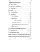
TABLE OF CONTENTS Section Page 1 FAMILIARIZING YOURSELF WITH THE DRIVE................................................................... 6 2 IMPORTANT PROGRAMMING INFORMATION.................................................................... 7 2.1 50 Hz Motors................................................................................................................. 7 2.2 Motor Current Setting..................................................................................................
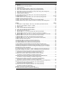
TABLE OF CONTENTS (CONTINUED) Table Page 1 Options .................................................................................................................................... 13 2 General Performance Specifications....................................................................................... 14 3 Electrical Ratings ....................................................................................................................
TABLE OF CONTENTS (CONTINUED) Figure Page 32 Accel/Decel #2 Connections and Drive Programming ............................................................ 41 33 Multi-Function Output Relay Connections............................................................................... 41 34 Analog Output Connections and Drive Programming ............................................................. 42 35 Analog Output Gain............................................................................................
UL NOTICE 115 Volt Drives Suitable for use on a circuit capable of delivering not more than 5 kA RMS symmetrical Amperes. 115 Volts maximum. Use copper conductors rated 75 °C. Suitable for operation in a maximum surrounding air temperature of 40 °C. 230 Volt Drives Suitable for use on a circuit capable of delivering not more than 5 kA RMS symmetrical Amperes. 230 Volts maximum. Use copper conductors rated 75 °C. Suitable for operation in a maximum surrounding air temperature of 40 °C.
1 FAMILIARIZING YOURSELF WITH THE DRIVE To get acquainted with the operation and programming, the drive does not need to be installed into the application or have a motor connected. In addition, drives rated for 3-phase AC Line input, can be operated with only 1-phase. To better understand the programmable features of the drive, review the Programmable Function List in Section 12, on pages 54 – 63.
2 IMPORTANT PROGRAMMING INFORMATION 2.1 50 Hz MOTORS This drive has been factory programmed to operate 60 Hz motors. For 50 Hz motor operation, set Function 0.00 to "0001" (50 Hz Motors). See Flow Chart (Figure 44), on page 51. 2.2 MOTOR CURRENT SETTING The motor current is factory set to the maximum drive rating, as shown in Table 3, on page 15. In order for the Motor Overload Protection to operate properly, the drive must be reprogrammed to the actual Motor Nameplate Current (see Function 0.01).
3 IMPORTANT APPLICATION INFORMATION 3.1 MOTOR WITH EXTERNAL FAN COOLING Most totally enclosed fan-cooled (TEFC) and open ventilated 3-phase AC induction motors will overheat if used beyond a limited speed range at full torque. Therefore, it FIGURE 2 MAXIMUM ALLOWED MOTOR TORQUE VS. SPEED is necessary to reduce motor load as speed is decreased. See Figure 2. Note: Some fan-cooled motors can be used over a wider speed range. Consult the motor manufacturer for details.
4 SAFETY WARNING Definition of Safety Warning Symbols Electrical Hazard Warning Symbol: Failure to observe this warning could result in electrical shock or electrocution. Operational Hazard Warning Symbol: Failure to observe this warning could result in serious injury or death. This product must be installed and serviced by a qualified technician, electrician, or electrical maintenance person familiar with its operation and the hazards involved.
5 INTRODUCTION Thank you for purchasing the KBDF Digital AC Drive. KB Electronics, Inc. is committed to providing total customer satisfaction by providing quality products that are easy to install and operate. The KBDF Series of Digital AC Drives are housed in IP-20 enclosures. They are designed to operate 1/8 thru 5 HP 208 – 230 and 400/460 Volt 50 & 60 Hz 3-phase AC and 1-phase PSC 1 induction motors.
5.1 STANDARD FEATURES ● Simplified Programming: Programmable parameters are organized into easy-to-understand intuitive groups. Factory programming available. ● Local/Remote Operation: When used with process control, the Local/Remote Key can be used to switch from process control to manual control if a process fault occurs. 1 ● Built-In EMC Filter : Complies with CE Council Directive 89/336/EEC Class A Industrial Standard. Reduces the footprint and cost compared to an external filter. See Note 1.
5.2 PERFORMANCE FEATURES ● High Performance Sensorless Flux Vector Control with Static Auto Tuning: Provides excellent speed regulation with high torque loads throughout the entire speed range. Auto energy savings at light loads. Smooth motor torque. ● Library of Advanced Algorithms: Custom programming and PLC functions for OEM applications. ● Power Start™: Provides more than 200% starting torque, which ensures startup of high frictional loads. ● Speed Range: Full torque control over a 50:1 speed range.
Option IODF Input/Output MultiFunction Expansion Module TABLE 1 OPTIONS Part No. Description Provides additional input/output and Multi-Function 9646 input/output of the drive. DIDF RS-232 and RS-485 Modbus RTU Communication Module Relay. Increases the functionality of the standard Allows direct communication between the drive and 9647 Modbus RTU protocol. Uses RS-232 and RS-485 Modbus RTU Communication Module. (Required for Drive-Link™.
TABLE 2 GENERAL PERFORMANCE SPECIFICATIONS Description 115 Volt AC Line Input Operating Range (Volts AC, 50/60 Hz) 208/230 Volt AC Line Input Operating Range (Volts AC, 50/60 Hz) 400/460 Volt AC Line Input Operating Range (Volts AC, 50/60 Hz) Maximum Load (% of Current Overload for 2 Minutes) Switching Frequency (kHz) Voltage Following Signal Input Range (Volts DC) Current Following Signal Input Range (mA DC) PWM Following Signal Input Range (kHz / % Duty Cycle) Analog Output (Volts DC) Output Frequency Res
TABLE 3 ELECTRICAL RATINGS KBDF-13 9623 0.5 (0.37) 1 KBDF-23 9688 0.5 (0.37) KBDF-23F1 9691 0.5 (0.37) KBDF-23D 9673 0.5 (0.37) KBDF-23P2 9694 0.5 (0.37) 115 Output Net Wt. Fuse or Circuit Maximum Continuous Maximum Breaker Maximum Rating Voltage Current Load Current (Amps AC) (Amps AC) (Volts AC) (RMS Amps/Phase) lbs kg 9.6 15 230 2.4 208/230 1 6 10 230 2.4 208/230 1 7 10 230 2.4 230 2.4 9.6 15 208/230 1 115 6 10 208/230 3 3.1 10 230 2.4 1 16 20 230 4.
6 DRIVE LAYOUT See Figure 3 for the Drive Layout. See Table 4, on page 17, for description of the Keypad, 4-Digit Display, LEDs, and Potentiometer. The drive contains 8 LEDs to provide indication of the drive’s status and operating mode (REM, LCL, FWD, REV, STOP, OL, PGM, Hz). The Keypad is used for Local Operation of the drive. For Remote Operation see Function Group 2, on page 57. To operate the drive using the Potentiometer, set Function 2.00 to "0001".
No. TABLE 4 DESCRIPTIONS OF 4-DIGIT DISPLAY, LEDs, KEYS, AND POTENTIOMETER Feature Description 1 4-Digit Display: Provides readout of drive status, operating parameters, and faults. 2 REM LED: Indicates that the drive is set for Remote Operation. 3 LCL LED: Indicates that the drive is set for Local (Keypad) Operation. 4 FWD LED: Indicates that the drive is set for Forward Direction. 5 REV LED: Indicates that the drive is set for Reverse Direction.
7 MOUNTING INSTRUCTIONS It is recommended that the drive be mounted vertically on a flat surface with adequate ventilation. Leave enough room above and below the drive to allow for AC Line, motor connections, and any other connections that are required. Care should be taken to avoid extreme hazardous locations where physical damage can occur.
FIGURE 5 CASE "B" DRIVES MECHANICAL SPECIFICATIONS (INCHES / mm) 4X Ø 0.225 5.72 RUN STOP FWD REV 7.357 7.825 187 199 KBDF SERIES 3.80 96.5 4.40 112 6.
8 ELECTRICAL CONNECTIONS The drive is designed with contactor-type feed-throughs to facilitate wring of the AC Line input, Motor, and Ground connections, as shown in Figures 7 – 13, on pages 22 – 24. See Table 5, on page 22. The removable cover allows access to the terminal blocks and jumpers for wiring and setting up the drive for Remote Operation in lieu of the Keypad (Local Operation).
FIGURE 6 GENERAL CONNECTION DIAGRAM 2 2 1 3 Notes: 1. Multi-Function Input Terminals (MFIT 1 – 5 on TB1 of the drive) are factory set for N.O. Contacts or NPN Transistors (J1 set to the "N.O. / NPN" position), which use the internal power supply. For NPN Transistors, which use an external power supply (5 – 24 Volts DC), set Jumper J1 to the "EXT" position. For PNP Transistor circuits, which use the internal power supply or an external power supply (5 – 24 Volts DC), set Jumper J1 to the "PNP" position.
TABLE 5 DRIVE TERMINAL BLOCK WIRE AND TIGHTENING TORQUE SPECIFICATIONS Maximum Recommended Wire Size Tightening (Cu) Torque (1) Description Location Model AWG mm2 Lbs-in kg-cm Multi-Function Input (2) TB1 on Drive and IODF (Under Cover) Terminals and Signals In/Out Multi-Function Output Relay 16 1.31 2.7 3.1 All 16 1.31 2.6 2.9 14 2.08 7 8.1 12 3.31 12 14 14 2.08 7 8.1 12 3.
Models KBDF-23D, 24D, 27D: Designed for 115 and 208/230 Volt 1-phase AC Line input. For 115 Volt Line input, connect the AC Line input hot lead to Terminal "L1" and the neutral lead to Terminal "N". For 208/230 Volt AC Line input, connect to Terminals "L1" and "L2". See Figure 8. Note: 230 Volts AC will be applied to the motor with 115 Volt AC Line input.
Models KBDF-42, 43, 45, 48: Designed for 400/460 Volt 3-Phase AC Line Input. Connect the AC Line Input to Terminals "L1", "L2", and FIGURE 12 MODELS KBDF-42, 43, 45, 48 AC LINE AND GROUND CONNECTIONS "L3". See Figure 12. 8.2 AC LINE INPUT FUSING The drive does not contain AC Line fuses. For the recommended fuse or circuit breaker rating, see Table 3, on page 15. Do not fuse motor leads. Most electrical codes require that each ungrounded conductor contain circuit protection.
8.4 REMOTE OPERATION The Drive is designed with a removable cover to access the Multi-Function Inputs and Outputs and jumpers to set up the drive for remote operation. It also allows access to install the optional accessories. See Table 6. Also see Table 7, on page 26. To remove the cover, press on the finger grips on both side corners of the cover until the retaining clips disengage from the base and lift it up.
Terminal Blocks TB1 on Drive 1 2 3 4 5 6 7 8 9 10 11 12 TB1 on IODF TB2 on Drive TB3 on IODF TABLE 7 1 DRIVE INPUT AND OUTPUT CONNECTIONS No. Description Specifications 1 Power Supply –5 Volts DC at 1 mA Max. 2 Power Supply +5 Volts DC at 1 mA Max.
8.4.1 START/STOP AND FORWARD/REVERSE The drive can be started and stopped using 2-Wire or 3-Wire Start/Stop Contacts connected to the Multi-Function Input Terminals. Also, some applications may require a jumper, which will provide automatic starting of the drive when either a forward or reverse contact is closed. See Figure 14, below, for the connections and drive programming. Application Note: A frequency command must also be given for the drive to run.
8.4.1.2 2-WIRE START/STOP Close the Start/Stop Contact to Start the drive. Open the Start/Stop Contact to the Stop the drive. See Figure 15, for connections and drive programming. FIGURE 15 2-WIRE START/STOP CONNECTIONS AND DRIVE PROGRAMMING Program Function Setting 1.00: Run/Stop-Forward/Reverse Control 0001: External Contacts* 7.04: Multi-Function Input Terminal 5 (TB1 Term. 9) 0010: N.O. Start (2-Wire or 3-Wire Start/Stop)* *Factory setting. 8.4.1.
8.4.1.4 FORWARD/STOP AND REVERSE/STOP Remote Forward/Stop and Reverse/Stop operation can be performed by connecting contacts to the Multi-Function Input Terminals. Close the Forward Contact to run the drive in the forward direction. Close the Reverse Contact to run the drive in the reverse direction. Open the contact to stop the drive. See Figure 17, for connections and drive programming. Connect the Start/Stop Contact to Terminal "9", which is factory set for N.O. Start ("0010").
8.4.2 FREQUENCY CONTROL The drive's output frequency can be controlled by various methods: 1. Analog Input (Voltage following, Current Following). See Section 8.4.2.1, below. 2. Remote Main Speed Potentiometer. See Section 8.4.2.2, on page 32. 3. Up/Down Frequency Control (using the Multi-Function Input Terminals). See Section 8.4.2.3, on page 34. 4. Preset Frequency (using the Multi-Function Input Terminals). See Section 8.4.2.4, on page 37. 5.
FIGURE 20 ANALOG INPUT JUMPER J2 SETTINGS MEMORY MODULE 8.4.2.1.1 VOLTAGE FOLLOWING Connect the 0 – ±5 or 0 – ±10 Volt DC Voltage Signal input to TB1 Terminal "3" and the common to TB1 Terminal "4". Set Jumper J2 to the corresponding signal input voltage (factory set to "5V" position). Connect the Start (Jumper) to TB1 Terminal "9", which is factory set for N.O.
8.4.2.1.2 CURRENT FOLLOWING Connect the 0 – 20 mA or 4 – 20 mA DC Current Signal input to TB1 Terminal "3" and the common to TB1 Terminal "4". Set Jumper J2 to "CUR" and be sure it is also set to "ANLG" and "5V". Connect the Start (Jumper) to TB1 Terminal "9", which is factory set for N.O. Start ("0010") and to either common TB1 Terminal "4" or "11" Set the signal Slope and Type and adjust the Gain, Offset, and Response Time as desired.
FIGURE 23 UNIDIRECTIONAL REMOTE MAIN SPEED POTENTIOMETER WITH START/STOP CONNECTIONS, JUMPER J2 SETTINGS, AND DRIVE PROGRAMMING Jumper J2 Settings Program Function Setting 1.00: Run/Stop-Forward/Reverse Control 0001: External Contacts* 2.01: Remote Frequency Control 0000: Analog Signal 1* 7.04: Multi-Function Input Terminal 5 (TB1 Term. 9) 0010: N.O. Start (2-Wire or 3-Wire Start/Stop)* 9.03: Analog Input 1 Type 0000: Unidirectional* *Factory setting.
Bidirectional Operation with Forward/Reverse Connect the high side of the Main Speed Potentiometer to TB1 Terminals "2" (+5 Volts), the wiper to TB1 Terminal "3" (Analog Signal Input), and the low side to TB1 Terminal "4" (Common). Connect the Start/Stop Contact to TB1 Terminal "9", which is factory set for N.O. Start ("0010"), and to either TB1 Terminal "4" or "11". Connect the Forward/Stop Contact to TB1 Terminal "7" and to either common TB1 Terminal "4" or "11".
Incremental Operation: For each activation of the Up Contact, the drive output frequency will increase incrementally, equal to the frequency set by Function 7.15 (factory set to 1.00 Hz). For each activation of the Down Contact, the drive output frequency will decrease incrementally, equal to the frequency set by Function 7.15 (factory set to 1.00 Hz).
Bidirectional Up/down Frequency Control Connect the Start (Jumper) to Multi-Function Input Terminal 9, which is factory set for N.O. Start ("0010"). Connect the Forward/Stop and Reverse/Stop Contacts to any Multi-Function Input Terminals "1" – "7". TB1 Terminals "3" and "4" have been arbitrarily chosen for Forward/Stop and Reverse Stop. The common of the contacts can be connected to either common TB1 Terminal "4" or "11". See Figure 27, for connections and drive programming.
8.4.2.4 PRESET FREQUENCY CONTROL The drive is factory programmed for 7 Preset Frequencies, which can be selected using remote contacts connected to Multi-Function Input Terminals "1", "2", and "3" (TB1 Terminals "5", "6", and "7"). See Table 8, for the terminals to select for the preset frequencies. The 7 Preset Frequencies are obtained using a combination of Multi-Function Input Terminals 1, 2, 1+2, 3, 1+3, 2+3, 1+2+3.
FIGURE 28 UNIDIRECTIONAL PRESET FREQUENCY SELECTION WITH 2-WIRE START/STOP CONNECTIONS AND DRIVE PROGRAMMING Program Function Setting 1.00: Run/Stop-Forward/Reverse Control 0001: External contacts 3.00: Stored Set Frequency (Hz) 00.00 Hz 7.00: Multi-Function Input Terminal 1 (TB1 Term. 5) 0000: Preset Frequency Operation* 7.01: Multi-Function Input Terminal 2 (TB1 Term. 6) 0001: Preset Frequency Operation* 7.02: Multi-Function Input Terminal 3 (TB1 Term. 7) 0002: Preset Frequency Operation* 7.
8.4.3 MULTI-FUNCTION INPUT TERMINALS The Multi-Function Input Terminals can be used control the drive for Reset, External Fault, and Accel/Decel #2. For NPN and PNP Circuits, see Appendix E, on page 70. 8.4.3.1 RESET It is advisable to connect a momentary normally open contact to Multi-Function Input Terminal "4". This allows the drive to be restarted after a fault has been cleared. See Figure 30, for connections and drive programming.
Connect the auxiliary equipment contact to any Multi-Function Input Terminal "1" – "7". TB1 Terminal "6" has been arbitrarily chosen for External Fault. The common of the circuit can be connected to either common TB1 Terminal "4" or "11". Operation: When the circuit is activated, the drive will "stop" and the display of the drive will show "EF-t".
FIGURE 32 ACCEL/DECEL #2 CONNECTIONS AND DRIVE PROGRAMMING Program Function Setting 1.00: Run/Stop-Forward/Reverse Control 0001: External Contacts* 7.04: Multi-Function Input Terminal 5 (TB1 Term. 9) 0005: Accel/Decel #2 7.16: Accel/Decel #2 Time (Seconds) 0.3 – 180.0 Seconds (10 Seconds*) *Factory setting. 8.4.4 MULTI-FUNCTION OUTPUT RELAY The Multi-Function Output Relay connections are located on TB2, as shown in Figure 33. To access TB2, remove the drive's cover. See Section 8.4, on page 25.
8.4.5 ANALOG OUTPUT An Analog Output is provided, which puts out a 0 – 5 Volt DC signal and will linearly follow the parameter programmed in Analog Output 1 Mode (Function 5.14). It can be used to monitor Output Frequency, Set Frequency, Motor Voltage, Bus Voltage, and Motor Current. See Figure 34, for connections and drive programming. See Figure 35, for Analog Output 1 Gain settings (factory set to 100%). FIGURE 34 ANALOG OUTPUT CONNECTIONS AND DRIVE PROGRAMMING Program Function Setting 5.
9 HIGH VOLTAGE DIELECTRIC WITHSTAND TESTING (HI-POT TEST) Testing agencies such as UL, CSA, etc., usually require that equipment undergo a hi-pot test. In order to prevent catastrophic damage to the drive, which has been installed in the equipment, the following procedure is recommended. A typical hi-pot test setup is shown in Figure 36. All drives have been factory hi-pot tested in accordance with UL requirements.
10 DRIVE OPERATION Before operating the drive, read Section 10.3, below, for instructions on the Keypad Operation. See Figure 3, on page 16, for the keypad layout. The 4-digit display can indicate various functions of the drive: Set Frequency, Motor RPM, Output Current and Voltage, Custom Units, Function Numbers, Function Codes or Values, and Fault Codes. See Section 11, on page 52. See Section 12, on page 54, for information on programming the drive.
10.4 FLOW CHARTS FOR IMPORTANT PROGRAMMING FUNCTIONS See Figures 37 – 44, on pages 45 – 51, for the flow charts to program important functions. The flow charts also serve as a guide to understand the programming procedure. Note: See Table 10, on pages 52 and 53, for a description of the Digital Readout codes. FIGURE 37 FLOW CHART TO PROGRAM MOTOR CURRENT FROM 6.7 AMPS TO 5.5 AMPS *Rating shown is for Models KBDF-27, KBDF-27F, KBDF-27D (2 HP, (1.5 kW)), and KBDF-29 (1-Phase).
FIGURE 38 FLOW CHART TO CHANGE SET FREQUENCY FROM 5.00 Hz TO 43.21 Hz* (DRIVE IN STOP MODE) RUN STOP *If Function 2.02 is set to "0000", frequency change requires pressing the ENTER Key. Throughout this sequence, you must proceed to the next step within 20 seconds, before the "Press Enter Key" step, or the display will revert back to "0500". The new value will be stored in Function 3.00.
FIGURE 39 FLOW CHART TO PROGRAM ACCEL TIME FROM 1.5 SECONDS TO 120 SECONDS *The factory setting of Accel Time (Function 3.03) is "1.5" seconds. Therefore, the left digits must be changed first since an Accel setting of "000.0" is not allowed.
FIGURE 40 FLOW CHART TO PROGRAM THE DRIVE TO DISPLAY MOTOR RPM *The factory setting of display Mode (Function 4.00) is Frequency ("0000").
FIGURE 41 FLOW CHART TO PROGRAM THE DRIVE TO DISPLAY CUSTOM UNITS "012.0" Notes: 1. The factory setting of Display Mode (Function 4.00) is Frequency ("0000"). 2. The factory setting of Custom Units Significant Digits (Function 4.01) is "0100". 3. The factory setting of Custom Units Display (Function 4.02) is Whole Numbers ("0000"). 4. The Custom Unit setting "012.0" will be displayed at full speed.
FIGURE 42 FLOW CHART SHOWING MOTOR CURRENT, MOTOR VOLTAGE, AND BUS VOLTAGE ADDED TO THE BASIC DISPLAY* RUN STOP *Functions 4.04, 4.05, and 4.06 set to "0001". FIGURE 43 FLOW CHART TO PROGRAM THE DRIVE FOR REMOTE OPERATION ONLY* *Disables Local (Keypad) Operation.
FIGURE 44 FLOW CHART TO PROGRAM THE DRIVE FOR 50 Hz MOTORS 51
11 4-DIGIT DISPLAY READOUT CODES The 4-digit display provides readout of drive status, operating parameters, and faults. See Table 10, below and on page 54, for the Digital Readout Codes displayed and their descriptions. WARNING! Do not depend on the LEDs or the 4-Digit Display to no longer be illuminated as a guaranteed power off condition. Be sure that the main power switch or circuit breaker is in the "OFF" position before servicing the drive.
TABLE 10 DIGITAL READOUT CODES (CONTINUED) Display Description Short Circuit Fault: Indicates that the drive detected a short circuit at the motor (phase-to-phase). AC Line Phase Loss Detection: Indicates that the drive has detected a loss of one of the phases in the 3-phase AC line input applied to Models KBDF-23P, 24P, 27P, 29, 42, 43, 45, 48. Data Enter Error: Indicates that the drive is in the Program Mode and a non-valid parameter change has been attempted.
12 PROGRAMMABLE FUNCTION LIST (Rev. A) All functions have been factory set, as shown in the tables on pages 55 – 63. The Detailed Programmable Function List is available – contact our Sales Department. Programming Mode: When the drive is put into the Programming Mode (see Figure 45) a Function No. will be displayed. A Function No. consists of a Group No. (digits on the left side of the decimal point) and a Group No. Code (digits on the right side of the decimal point).
Function Group 0: Motor and Drive Parameters Function No. Description 0.00 * Rated Motor Frequency (Hz) 0.01 * 0.02 * Motor Nameplate Current (Amps) Reserved 0.03 * Torque Mode 0.04 * GFCI Operation (2) 0.05 * 0.06 * Motor Nameplate Frequency (Hz) Motor Nameplate Voltage (% Drive Output) (5) (3, 4) Range/Code 0000: 60 Hz 0001: 50 Hz 0002: Special (Set by 0.
Function Group 1: Run/Stop Mode Function No. Description 1.00 * Run/Stop-Forward/Reverse Control (1) 1.01 * Forward/Reverse Control 1.02 * Motor Direction 1.03 * Start Command 1.04 * Restart Mode 1.05 * Auto/Manual Start Mode 1.06 * 1.07 * 1.08 * Ride-Through Time (Seconds) Number of Restart Attempts Start Delay Time (Seconds) 1.09 * Stop Mode 1.10 * 1.11 1.12 1.
Function Group 2: Frequency Control Function No. Description 2.00 * Local Frequency Control 2.01 * Remote Frequency Control** 2.02 * Up Key, Down Key Operation Mode 2.
Function Group 4: Digital Display Modes Function No. Description 4.00 Display Mode 4.01 Custom Units (Significant Digits) 4.02 Custom Units Display 4.03 Display in Stop Mode 4.04 Motor Current Display (2, 3) 4.05 Motor Voltage Display (2, 3) 4.06 Bus Voltage Display (2, 3) 4.07–412 Reserved Factory User Range/Code Setting Setting 0000: Frequency 0001: RPM (1) 0000 0002: Custom Units (Default is "0100") 0 – 9999 100 0000: Whole Numbers (XXXX) 0001: One Decimal Place (XXX.
Function Group 6: Drive Status and Reset Function No. 6.00 * 6.01 * 6.02 * 6.03 * 6.04 * 6.05 * 6.06–6.09 Description Drive ID Software Version Drive Horsepower Fault Log 1 Fault Log 2 Fault Log 3 Reserved 6.10 ** Reset Drive to Factory Setting 6.11 ** Program Location 6.12 ** Program Number 6.13 ** Memory Copy Operation 6.14 ** On-board Memory Program Number 6.15 ** Memory Module Program Number 6.
Function Group 7: Multi-Function Input Terminals Function No. Description Range/Code 7.00 * Multi-Function Input 1 (Terminal 5) (1) 7.01 * Multi-Function Input 2 (Terminal 6) (1) 0000: 0001: 0002: 0003: 7.02 * Multi-Function Input 3 (Terminal 7) (1) 0004: 7.03 * Multi-Function Input 4 (Terminal 8) (1) 7.04 * Multi-Function Input 5 (Terminal 9) (1) 7.05 * (1, 4) 0005: 0006: 0007: 0008: 0009: 0010: 7.06 * 7.07 7.08 7.09 7.10 7.11 7.12 7.
Function Group 9 – Analog Input Signal Operation Function No. Description 9.00 Analog Input 1 Gain (%) 9.01 9.02 9.03 9.04 9.05 9.06 9.07 9.
Function Group 10: Communication Mode (DIDF Option Board Required) Function No. Description 10.00 * Assigned Comm. Station Number 10.01–10.03 Reserved 10.04 Communications Watchdog Timer 10.05 Watchdog Timeout (Seconds) 10.06 Reserved 10.07 Operational Command 10.08 Drive Status 10.09 Drive Status Description 10.10 ** Communications Error Count 10.11 ** Motor Voltage 10.12 ** Motor Current 10.13 ** Bus Voltage 10.14 ** Motor Frequency 10.15–10.
Function Group 11: Advanced Vector Control (Encoder and DIDF Option Board Required) Function Description No. 11.00–1.13 Reserved Range/Code — Factory User Setting Setting — — Range/Code — Factory User Setting Setting — — Function Group 12: Reserved Functions Function No. Description 12.00–12.
APPENDIX A OPTIONAL IODF INPUT/OUTPUT MULTI-FUNCTION EXPANSION MODULE (PART NO. 9646) The IODF Input/Output Multi-Function Expansion Module provides additional input/output lines to increases the functionality of the standard inputs/outputs of the drive. An additional MultiFunction Output Relay is also provided. PRESET FREQUENCIES The drive is factory programmed for 7 Preset Frequencies, which can be selected using remote contacts connected to the Multi-Function Input Terminals "1" – "7".
Terminal Block (TB1 on IODF) TABLE 12 IODF INPUT AND OUTPUT CONNECTIONS No. Description Specifications Open Collector 13 NPN Output N.O. Contacts or NPN / PNP Transistors 7 Preset Frequencies, Up Frequency Command, Down Frequency Command, Accel/Decel #2, Forward / Stop Command, Reverse / Stop Command, External Fault (N.O. Contact), Reset, N.O. Start (2-Wire or 3-Wire Start/Stop), N.C. Stop (3-Wire Start/Stop), External Fault (N.C.
TABLE 14 IODF MULTI-FUNCTION INPUT TERMINAL, FUNCTION, AND FACTORY CODE ASSIGNMENT Multi-Function Input Terminal* 6 7 Number On Terminal Block 14 15 Function 7.05 7.06 Factory Code Setting 0003 0004 Code Description Up Frequency Command Down Frequency Command *Each Multi-Function Input Terminal is controlled by a specific Function. Although factory set to a specific code, they can also be reprogrammed to any code "0000" – "0012" listed in Table 12, on page 65. See Function Group 7, on page 60.
APPENDIX B OPTIONAL DIDF MODULE (PART NO. 9647) RS232 AND RS-485 MODBUS RTU COMMUNICATION The optional DIDF RS-232 and RS-485 Modbus RTU Communication Module allows direct communication between the drive and Modbus RTU protocol. Uses RS-232 and RS-485 Modbus RTU Communication Module. (Required for Drive-Link™.) See Figure 47.
APPENDIX C OPTIONAL MEMORY MODULE (PART NO. 9634) The optional plug-in memory module can store up to 4 programs for cloning and archiving. This is in addition to the (4) on-board programs. The drive is factory set to use Program 1 on the drive or Memory Module (Function 6.12 set to "0001". For Program 2, Set Function 6.12 to "0002". For Program 3, set Function 6.12 to "0003". For Program 4, set Function 6.12 to "0004". Remove the cap to install the Memory Module. See Figure 48.
APPENDIX D OPTIONAL DYNAMIC BRAKE MODULE (PART NO. XXXX) The Dynamic Brake Module Provides dynamic braking of the motor. It is externally mounted. Case "B" drives only. Connect the positive (+) lead to Terminal "B+" and the negative (-) lead to Terminal "B-". See Figure 49.
APPENDIX E MULTI-FUNCTION INPUT TERMINALS WITH NPN AND PNP TRANSISTOR CIRCUITS NPN and PNP transistors can be used for the Multi-function Input Terminals using the internal power supply or an external power supply. See Figures 50 – 53.
NOTES 71
LIMITED WARRANTY For a period of 18 months from the date of original purchase, KB Electronics, Inc. will repair or replace without charge, devices which our examination proves to be defective in material or workmanship. This warranty is valid if the unit has not been tampered with by unauthorized persons, misused, abused, or improperly installed, and has been used in accordance with the instructions and/or ratings supplied. The foregoing is in lieu of any other warranty or guarantee, expressed or implied.
RECONDITIONING THE BUS CAPACITORS If this drive has been in storage for over one year it is necessary to recondition the power supply bus capacitors. To recondition the bus capacitors, apply the AC Line, with the drive in the Stop Mode, for a minimum of one hour. Not following this procedure will cause the bus capacitors to fail. (A40194) – Rev.
MODEL KBDF-29 (1P) SUPPLEMENT IMPORTANT: The KBDF Series Installation and Operation Manual (Part No. A40177) must be read and understood before attempting to operate this drive. For further assistance, contact our Sales Department at 954-346-4900 or Toll Free at 800-221-6570 (outside Florida). DESCRIPTION: Model KBDF-29 (1P) has been added to the KBDF Series of drives. This model is designed to accept 1-phase 208/230 Volt AC line input only.