
Manual

31
4.8 ANALOG SIGNAL OUTPUT
Two analog signal outputs are provided, which will linearly follow the parameter
programmed in Analog output 1 Mode (Function No. 8.06) and Analog Output 2
Mode (Function No. 8.08). They can be used to monitor Motor Frequency, Set
Frequency, Motor Voltage, Bus Voltage, and Motor Current. See Figure 24 for
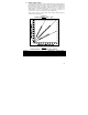
Analog Output 1 and 2 Gain settings (factory set to 100%). See Table 18 for
Analog Outputs 1 and 2 electrical ratings. See Figure 25, on page 32, for
connections. See Table 19, on page 32, for drive programming.
Analog Output 1 provides a voltage signal output. Analog Output 2 provides a
voltage or current signal output.
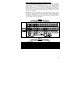
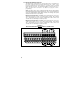
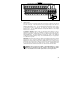
FIGURE 24
ANALOG OUTPUTS "1" AND "2" GAIN
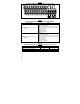
TABLE 18
ANALOG OUTPUTS "1" AND "2" ELECTRICAL RATINGS
Parameter Specification Factory setting
Analog Outputs 1 and 2 Voltage Range (Volts DC) 0 – 5 0 – 5
Analog Output 2 Current Range (mA DC) 0 – 20, 4 – 20 –
Analog Output 2 Impedance for Current Mode (Ω) 150 –