
Manual

30
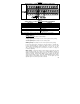
TABLE 16
ANALOG INPUT "2" ELECTRICAL RATINGS
Parameter Specification Factory setting
Voltage Range (Volts DC) 0 – ±2.5 thru 0 – ±25 0 – 5
MAX2 Scaling Trimpot Range (Volts DC) 0 – 24 5
Current Range (mA DC) 0 – 20* –
Input Impedance for Current Mode (Ω) 270 –
PWM (kHz, Duty Cycle) 0.15 – 1, 0 – 100 –
*If using 4 – 20 mA DC signal input, the offset setting in Function No. 9.07 must be increased
from "0%" (factory setting) to "20%". Set Jumper J1 to the "CUR" position.
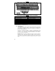
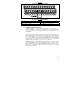
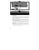
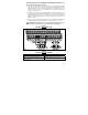
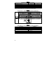
FIGURE 23
ANALOG INPUT "2" SIGNAL CURRENT FOLLOWING CONNECTIONS
+
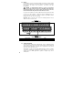
TABLE 17
ANALOG INPUT "2" SIGNAL CURRENT FOLLOWING PROGRAMMING
Function No. Code/Range
2.00: Frequency Control 0003: Analog Signal 2
9.05: Analog Input 2 Gain 0 – 500: Set to the Desired Gain
7.04: Multi-Function Input Terminal 5 0010: N.O. Start*
9.06: Analog Input 2 Slope
0000: Positive
0001: Negative
9.07: Analog Input 2 Offset 0 – 100: Set to the Desired Offset
9.08: Analog Input 2 Type 0000: Analog Voltage or Current
9.09: Analog Input 2 Response Time (mSec) 2 – 100: Set to the Desired Time
*Factory setting.