INSTALLATION AND OPERATION MANUAL IODA INPUT/OUTPUT MULTI-FUNCTION BOARD (Part No. 9668) Use with Models KBDA-24D, 27D, 29, 45, 48 RoHS See Safety Warning, on page 4. The information contained in this manual is intended to be accurate. However, the manufacturer retains the right to make changes in design, which may not be included herein. ©2008 KB Electronics, Inc.
TABLE OF CONTENTS Section Page 1 Safety Warning................................................................................................................. 4 2 Introduction ...................................................................................................................... 5 3 Installation Instructions ..................................................................................................... 7 4 Electrical Connections ........................................................
TABLE OF CONTENTS (CONTINUED) Figure Page 1 IODA Layout..................................................................................................................... 6 2 KBDA Layout.................................................................................................................... 7 3 Exploded View of KBDA and IODA Assembly .................................................................. 8 4 Preparing the Drive for Installation of the IODA ...........................................
● ● ● ● ● ● ● ● ● ● 1 ITEMS INCLUDED IN THIS PACKAGE IODA Input/Output Multi-Function Board. Small Mounting Base (for Model KBDA-24D only). Large Mounting Base (for Models KBDA-27D, 29, 45, 48). One 6-32 X ½" and one 6-32 X 1" Socket Head Cap Screw (for Small Mounting Base). Two 6-32 X 1½ " Socket Head Cap Screws (for Large Mounting Base). 7/64" Allen key. IODA Input/Output Multi-Function Board Installation and Operation Manual.
2 INTRODUCTION Thank you for purchasing the IODA Input/Output Multi-Function Board. KB Electronics, Inc. is committed to providing total customer satisfaction by producing quality products that are easy to install and operate. The IODA Input/Output Multi-Function Board provides a variety of functions which include preset frequency, up/down frequency control, signal isolation, isolated output voltage for controlling auxiliary devices, output relay contacts, and open collector outputs.
FIGURE 1 IODA LAYOUT *The IODA kit contains 2 mounting bases. Use the small base for Model KBDA-24D and the large base for Models KBDA-27D, 29, 45, 48.
FIGURE 2 KBDA LAYOUT *Model KBDA-24D shown. Layout of Models KBDA-27D, 29, 45, 48 varies slightly. 3 INSTALLATION INSTRUCTIONS The IODA is designed to be installed onto the KBDA PC board with a mounting base and screws provided. The ribbon cable in the KBDA contains a connector which is to be plugged into the mating connector on the IODA. See Figures 8 and 9, on pages 11 and 12, showing the IODA installed onto the KBDA PC board.
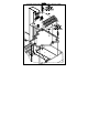
FIGURE 3 EXPLODED VIEW OF KBDA AND IODA ASSEMBLY (KBDA-24D SHOWN) 8
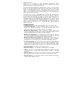
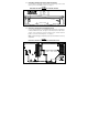
3.1 PREPARING THE DRIVE FOR INSTALLATION OF THE IODA Use the Allen Key (supplied) to remove the two socket head cap screws located at the top corners of the KBDA PC board. See Figure 4. FIGURE 4 PREPARING THE DRIVE FOR INSTALLATION OF THE IODA* *Model KBDA-24D shown. Layout of Models KBDA-27D, 29, 45, 48 varies slightly. 3.3 INSTALLING THE IODA ONTO THE MOUNTING BASE Use the small mounting base for Model KBDA-24D and the large mounting base for Models KBDA-27D, 29, 45, 48.
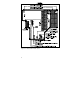
3.4 INSTALLING THE IODA INTO THE DRIVE Place the IODA in the area where it is to be installed. Be sure the ribbon cable is routed underneath the mounting base. Align the two snap-ins of the mounting base with the two holes on the KBDA PC board and press firmly until the mounting base is secured onto the KBDA PC board. See Figure 6. Use the 6-32 X ½" and 6-32 X 1" screws for the small Mounting Base (see Figure 8, on page 11).
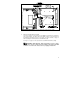
3.6 IODA INSTALLED INTO THE DRIVE After completing the installation, the IODA mounted in Model KBDA -24D will resemble Figure 8 and the IODA mounted in Models KBDA-27D, 29, 45, 48 will resemble Figure 9, on page 12.
FIGURE 9 IODA INSTALLED INTO MODELS KBDA-27D*, 29, 45, 48 *Layout of Model KBDA-27D varies slightly.
4 ELECTRICAL CONNECTIONS See Sections 4.1 – 4.11, on pages 15 – 38, for the electrical connections to the IODA. See Figure 10, below, for Terminal Block TB1 Layout. Common Terminals "8", "12", "14", "16", "18", "20", and "22" (shown shaded) are all internally connected and can be used with the Multi-Function Input Terminals "1" – "7", Signal Inputs 1 and 2, and Signal Outputs 1 and 2. See Table 1, on page 14, for Terminal Block TB1 Wire and Tightening Torque Specifications.
Multi-Function Input Terminal Codes (Function Group 7) TABLE 1 TERMINAL BLOCK TB1 WIRE AND TIGHTENING TORQUE SPECIFICATIONS Maximum Wire Size (Cu) Recommended Tightening Torque AWG mm2 lbs-in kg-cm 16 1.3 6 7 TABLE 2 FUNCTIONS, FEATURES, AND TERMINAL ASSIGNMENT Terminal Assignment MultiRelay Multi-Function Input Terminals1 Power Function Analog Analog Outputs 3 (Digital Inputs) Supply2 Outputs2 Outputs2 Inputs2 23 19 15 11 1–7 8 RY1 Analog Analog Open 0000: Preset Frequency Operation1 Common N.O.
TABLE 3 MULTI-FUNCTION INPUT TERMINAL, FUNCTION NO., AND CODE ASSIGNMENT MFIT 1 2 3 4 5 6 7 Function No. 7.00 7.01 7.02 7.03 7.04 7.05 7.06 Factory Code 0000 0001 0002 0009 0010 0003 0004 Setting Preset Preset Preset 2-Wire Up Down Code Frequency Frequency Frequency Reset N.O. Frequency Frequency Description Operation Operation Operation Start/Stop Command Command Each Multi-Function Input Terminal is controlled by a specific Function No.
4.1.1 UNIDIRECTIONAL (FORWARD) PRESET FREQUENCY OPERATION See Figures 11 and 12, on page 17, for connections. See Tables 5 and 6, on pages 17 and 18, for drive programming. Connect the Preset Frequency Switches or Contacts to Multi-Function Input Terminals "1" – "3". For 2-Wire Start/Stop, connect the switch or contact to Multi-Function Input Terminal "5", as shown in Figure 11, on page 17. Terminal "5" is factory set for N.O Start ("0010").
FIGURE 11 UNIDIRECTIONAL PRESET FREQUENCY SELECTION WITH 2-WIRE START/STOP CONNECTIONS Note: Use Function Nos. 7.07 – 7.13 to program the desired Preset Frequencies. TABLE 5 UNIDIRECTIONAL PRESET FREQUENCY SELECTION WITH 2-WIRE START/STOP PROGRAMMING Function No. Code/Range 1.00: Run/Stop-Forward/Reverse Control 0001: External Contacts 3.00: Stored Set Frequency 00.00 Hz 7.00: Multi-Function Input Terminal 1 0000: Preset Frequency Operation* 7.
TABLE 6 UNIDIRECTIONAL PRESET FREQUENCY SELECTION WITH 3-WIRE START/STOP PROGRAMMING Function No. Code/Range 1.00: Run/Stop-Forward/Reverse Control 0001: External Contacts 3.00: Stored Set Frequency 00.00 Hz 7.00: Multi-Function Input Terminal 1 0000: Preset Frequency Operation* 7.01: Multi-Function Input Terminal 2 0001: Preset Frequency Operation* 7.02: Multi-Function Input Terminal 3 0002: Preset Frequency Operation* 7.04: Multi-Function Input Terminal 5 0010: N.O. Start* 7.
TABLE 7 BIDIRECTIONAL PRESET FREQUENCY SELECTION PROGRAMMING Function No. Code/Range 1.00: Run/Stop-Forward/Reverse Control 0001: External Contacts 3.00: Stored Set Frequency 00.00 Hz 7.00: Multi-Function Input Terminal 1 0000: Preset Frequency Operation* 7.01: Multi-Function Input Terminal 2 0001: Preset Frequency Operation* 7.02: Multi-Function Input Terminal 3 0002: Preset Frequency Operation* 7.04: Multi-Function Input Terminal 5 0010: N.O. Start* 7.
Note: Use a maintained switch or contact for Start/Stop. If a Start/Stop Switch or Contact is not used, a jumper must be installed between Terminals "5" and "8". Free-Running Operation: Close the Start/Stop Switch or Contact to put the drive into the Run Mode. When the Up Switch or Contact is closed, the drive output frequency will increase for the duration of the switch or contact closure. When the Up Switch or Contact is opened, the drive output frequency will stop increasing.
TABLE 8 UNIDIRECTIONAL UP/DOWN FREQUENCY CONTROL PROGRAMMING Function No. Code/Range 1.00: Run/Stop-Forward/Reverse Control 0001: External Contacts 2.00: Frequency Control 0005: Up/Down Using MFITs 7.04: Multi-Function Input Terminal 5 0010: N.O. Start* 7.05: Multi-Function Input Terminal 6 0003: Up Frequency Command* 7.06: Multi-Function Input Terminal 7 0004: Down Frequency Command. 7.14: Up/Down Frequency Control Mode 0000: Free-Running 0001: Incremental 7.15: Increment of Up/Down Frequency** 0.01 – 30.
FIGURE 15 BIDIRECTIONAL UP/DOWN FREQUENCY CONTROL CONNECTIONS TABLE 9 BIDIRECTIONAL UP/DOWN FREQUENCY CONTROL PROGRAMMING Function No. Code/Range 1.00: Run/Stop-Forward/Reverse Control 0001: External Contacts 2.00: Frequency Control 0005: Up/Down Using MFITs 7.02: Multi-Function Input Terminal 3 0006: Forward/Stop Command 7.03: Multi-Function Input Terminal 4 0007: Reverse/Stop Command 7.04: Multi-Function Input Terminal 5 0010: N.O. Start* 7.
FIGURE 16 ACCEL/DECEL "2" CONENCTIONS TABLE 10 ACCEL/DECEL "2" PROGRAMMING Function No. Code/Range 7.05: Multi-Function Input Terminal 6 0005: Accel/Decel 2 7.16: Accel/Decel 2 Time 0.3 – 180.0: Set to Desired Time* *Factory set to 1.5 seconds. 4.4 FORWARD/STOP-REVERSE/STOP Remote Forward/Stop and Reverse/Stop operation can be performed by connecting switches or contacts to the Multi-Function Input Terminals. See Figure 17, on page 24, for connections. See Table 11, on page 24, for drive programming.
FIGURE 17 FORWARD/STOP-REVERSE/STOP CONNECTIONS TABLE 11 FORWARD/STOP-REVERSE/STOP PROGRAMMING Function No. Code 1.00: Run/Stop-Forward/Reverse Control 0001: External Contacts 7.02: Multi-Function Input Terminal 3 0006: Forward/Stop Command 7.03: Multi-Function Input Terminal 4 0007: Reverse/Stop Command 7.04: Multi-Function Input Terminal 5 0010: N.O. Start* *Factory setting. 4.
APPLICATION NOTES FOR AUTO/MANUAL START MODE (FUNCTION NO. 1.05) After the Extenal Fault has been Cleared: 1. If the drive is set for Manual Start Mode ("0000" (factory setting)), Manual Start with Ride-Through ("0001"), or Auto Start After Undervoltage Fault Clears ("0002"), it will have to be manually restarted after the external fault has been cleared. Use the Reset Key on the Keypad or the external Reset Switch or Contact to restart the drive. 2.
4.6 RESET It is advisable to connect a momentary normally open switch or contact to MultiFunction Input Terminal "4". This allows the drive to be restarted after a fault has been cleared. See Figure 19 for connections. See Table 13 for drive programming.
Local/Remote Operation: When using the IODA with signal following or remote start/stop, it is desirable to program the drive for Local/Remote Operation. In this mode, the drive frequency setting can be toggled between a process signal and the keypad using the JOG-LCL/REM Key. The following functions can be switched between "remote" and "local" (Keypad) operation: Start/Stop, Forward/Reverse, Analog Signal Inputs 1 and 2, and Up/Down Frequency Control. Set Jog-Local/Remote (Function No. 2.
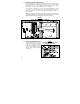
FIGURE 21 ANALOG INPUT "1" AND "2" SIGNAL GAIN AND OFFSET WITH NEGATIVE SLOPE (HIGH-TO-LOW SIGNAL) (FUNCTION NO. 9.01 OR 9.06 SET TO "0001") ANALOG INPUT "1" See Table 14 for Analog Input 1 electrical ratings. Connect the signal input to Terminal "19" and the common to Terminal "20". Connect the Start (Jumper) to Terminal "5", which is factory set for N.O. Start ("0010") and to any available common terminal ("8", "12", "14", "16", "18" "20", "22"). See Figure 22, on page 29, for connections.
FIGURE 22 ANALOG INPUT "1" SIGNAL VOLTAGE FOLLOWING CONNECTIONS + TABLE 15 ANALOG INPUT "1" SIGNAL VOLTAGE FOLLOWING PROGRAMMING Function No. Code/Range 2.00: Frequency Control 0002: Analog Signal 1 9.00: Analog Input 1 Gain 0 – 500: Set to the Desired Gain 7.04: Multi-Function Input Terminal 5 0010: N.O. Start* 0000: Positive 9.01: Analog Input 1 Slope 0001: Negative 9.02: Analog Input 1 Offset 0 – 100: Set to the Desired Offset 0000: Unidirectional 9.03: Analog Input 1 Type 0001: Bidirectional 9.
TABLE 16 ANALOG INPUT "2" ELECTRICAL RATINGS Parameter Specification Factory setting Voltage Range (Volts DC) 0 – ±2.5 thru 0 – ±25 0–5 MAX2 Scaling Trimpot Range (Volts DC) 0 – 24 5 Current Range (mA DC) 0 – 20* – Input Impedance for Current Mode (Ω) 270 – PWM (kHz, Duty Cycle) 0.15 – 1, 0 – 100 – *If using 4 – 20 mA DC signal input, the offset setting in Function No. 9.07 must be increased from "0%" (factory setting) to "20%". Set Jumper J1 to the "CUR" position.
4.8 ANALOG SIGNAL OUTPUT Two analog signal outputs are provided, which will linearly follow the parameter programmed in Analog output 1 Mode (Function No. 8.06) and Analog Output 2 Mode (Function No. 8.08). They can be used to monitor Motor Frequency, Set Frequency, Motor Voltage, Bus Voltage, and Motor Current. See Figure 24 for Analog Output 1 and 2 Gain settings (factory set to 100%). See Table 18 for Analog Outputs 1 and 2 electrical ratings. See Figure 25, on page 32, for connections.
FIGURE 25 ANALOG OUTPUTS "1" AND "2" CONNECTIONS TABLE 19 ANALOG OUTPUTS "1" AND "2" PROGRAMMING Function No. Code/Range 0000: Motor Frequency 0001: Set Frequency 0002: Motor Voltage 8.06: Analog Output 1 Mode 0003: Bus Voltage 0004: Motor Current 8.07: Analog Output 1 Gain 0 – 200: Set to the Desired Gain 0000: Motor Frequency 0001: Set Frequency 8.08: Analog Output 2 Mode 0002: Motor Voltage 0003: Bus Voltage 0004: Motor Current 0000: 0 – 5 Volts DC 8.
4.9 REMOTE MAIN SPEED POTENTIOMETER A remote Main Speed Potentiometer (5 kΩ) can be used in lieu of the Keypad or the Built-In Potentiometer on the drive to control motor speed. The potentiometer can be connected for Unidirectional Operation, Bidirectional Operation with center off, or Bidirectional Operation with Forward/Reverse Switches or Contacts.
TABLE 20 REMOTE UNIDIRECTIONAL MAIN SPEED POTENTIOMETER PROGRAMMING Function No. Code 1.00: Run/Stop-Forward/Reverse Control 0001: External Contacts 2.00: Frequency Control 0002: Analog Signal 1 7.04: Multi-Function Input Terminal 5 0010: N.O. Start* *Factory setting. BIDIRECTIONAL OPERATION WITH START/STOP (Use Analog Input "1" Only) Connect the Main Speed Potentiometer to Terminals "9" (+5 Volts), "19" (Analog Input 1), and "10" (-5 Volts).
BIDIRECTIONAL OPERATION WITH FORWARD/REVERSE: Connect the Main Speed Potentiometer to Terminals "9" (+5 Volts), "19" (Analog Input 1), and "8" (Common) (Terminals "12", "14", "16", "18" or "22" can also be used for Common). Connect the Forward Switch or Contact to a Multi-Function Input Terminal "1" – "7". Connect the Reverse Switch or Contact to a MultiFunction Input Terminal "1" – "7". Connect the Start (Jumper) to Terminal "5", which is factory set for N.O.
4.10 MULTI-FUNCTION OUTPUT RELAYS Two Multi-Function Output Relays are provided, which can be programmed for Run, Fault, Target Frequency, Frequency Threshold Level (> 8.04 – 8.05), Frequency Threshold Level (< 8.04 + 8.05), I2t or I•t Fault, Load Loss, External Fault, and Motor Overload. The maximum allowable contact load current is 1 Amp. See Figure 29 for connections. See Table 23, on page 37, for drive programming.
TABLE 23 MULTI-FUNCTION OUTPUT RELAY CONTACTS PROGRAMMING Function No. Code 0000: Run 0001: Fault 0002: Target Frequency 0003: Frequency Threshold Level (> 8.04 – 8.05) 8.00: Multi-Function Output Relay 1 0004: Frequency Threshold Level (< 8.04 + 8.05) 0005: I2t or I•t Fault 0006: Load Loss 0007: External Fault 0008: Motor Overload 0000: Run 0001: Fault 0002: Target Frequency 0003: Frequency Threshold Level (> 8.04 – 8.05) 0004: Frequency Threshold Level (< 8.04 + 8.05) 8.
FIGURE 30 MULTI-FUNCTION OPEN COLLECTOR OUTPUT CONNECTIONS TABLE 24 MULTI-FUNCTION OPEN COLLECTOR OUTPUT PROGRAMMING Function No. Code 0000: Run 0001: Fault 0002: Target Frequency 0003: Frequency Threshold Level (> 8.04 – 8.05) 8.02: Multi-Function Open Collector 0004: Frequency Threshold Level (< 8.04 + 8.05) Output 1 0005: I2t or I•t Fault 0006: Load Loss 0007: External Fault 0008: Motor Overload 0000: Run 0001: Fault 0002: Target Frequency 0003: Frequency Threshold Level (> 8.04 – 8.05) 8.
FIGURE 31 TYPICAL APPLICATION FOR OPEN COLLECTOR OUTPUT + 5 OPERATION After the drive has been properly setup and all connections completed, the start-up procedure can begin. If the AC power has been properly brought to the drive, the PWR LED will illuminate green. The red STATUS LED will indicate the drive's status, as described in Section 7, on page 43. See Table 26, on page 40, for the Digital Readout Codes. See the KBDA Installation and Operation Manual for other Digital Readout Codes of the drive.
TABLE 26 DIGITAL READOUT CODES Description Display Current Source Trip: Indicates that the current signal output (from the IODA) has been opened. IODA Error: Indicates that communication with the IODA. the drive has lost External Fault Trip: Indicates that an external fault has occurred at one of the MFITs of the IODA. Function Nos. 7.00 – 7.06 set to "0008". 6 PROGRAMMABLE FUNCTION SUMMARY LIST See the KBDA Series Installation and Instruction Manuals for other Programmable Functions.
FUNCTION GROUP 7 MULTI-FUNCTION INPUT TERMINALS Function No. Description 7.00 * Multi-Function Input Terminal 11 7.01 * Multi-Function Input Terminal 21 7.02 * Multi-Function Input Terminal 31 7.03 * Multi-Function Input Terminal 41 7.04 * Multi-Function Input Terminal 51 7.05 * Multi-Function Input Terminal 61 7.06 * 7.07 7.08 7.09 7.10 7.11 7.12 7.13 7.
FUNCTION GROUP 8 MULTI-FUNCTION OUTPUT RELAYS AND OUTPUT SIGNAL OPERATION Function Factory Actual No. Description Range/Code Setting Setting Multi-Function Output 8.00 * Relay 1 (Terminals 23 – 25) Multi-Function Output 8.01 * Relay 2 (Terminals 26 – 28) Multi-Function Open 8.02 * Collector Output 1 (Terminals 11, 12) Multi-Function Open 8.03 * Collector Output 2 (Terminals 13, 14) 8.04 8.05 Frequency Set Point (Hz) Frequency Bandwidth (± Hz) 0000: Run 0001: Fault1 0002: Target Frequency (8.04 ± 8.
FUNCTION GROUP 9 ANALOG INPUT SIGNAL OPERATION Function Factory Actual No. Description Range/Code Setting Setting 1 9.00 Analog Input 1 Gain (%) 0 – 500 100 0000: Positive 0000 9.01 Analog Input 1 Slope1 0001: Negative Analog Input 1 Offset 0 – 100 0 9.02 (%)1 0000: Unidirectional 0000 9.03 Analog Input 1 Type1 0001: Bidirectional Analog Input 1 9.04 2 – 100 2 Response Time (mSec)1 9.05 Analog Input 2 Gain (%)2 0 – 500 100 0000: Positive 0000 9.
LIMITED WARRANTY For a period of 18 months from the date of original purchase, KB Electronics, Inc. will repair or replace without charge, devices which our examination proves to be defective in material or workmanship. This warranty is valid if the unit has not been tampered with by unauthorized persons, misused, abused, or improperly installed and has been used in accordance with the instructions and/or ratings supplied. The foregoing is in lieu of any other warranty or guarantee, expressed or implied.