
F Manual


B. MOUNTING THE SIVF ONTO THE KBVF
See figure 3, SIVF Mounting Diagram.
See figures 4A and 4B, SIVF Mechanical Specifications, on pages 7 and 8.
The SIVF is installed onto the KBVF using (2) two 6-32 X 1/2” screws provided.
Note: The screws are a combination head type which allow the use of a readily avail-
able #1 or #2 phillips or slotted head screwdriver.
Note: Before installing the SIVF be sure the wiring to the KBVF has been completed.
See section II, Installation Instructions, on page 3
1. Align the SIVF mounting holes with the tapped holes on the KBVF heat sink and
insert the screws through the SIVF mounting holes.
2. Using a screwdriver, fasten both screws until the SIVF is secured to the KBVF (8
in-lbs max). Do not over tighten screws or damage may result to SIVF cover.
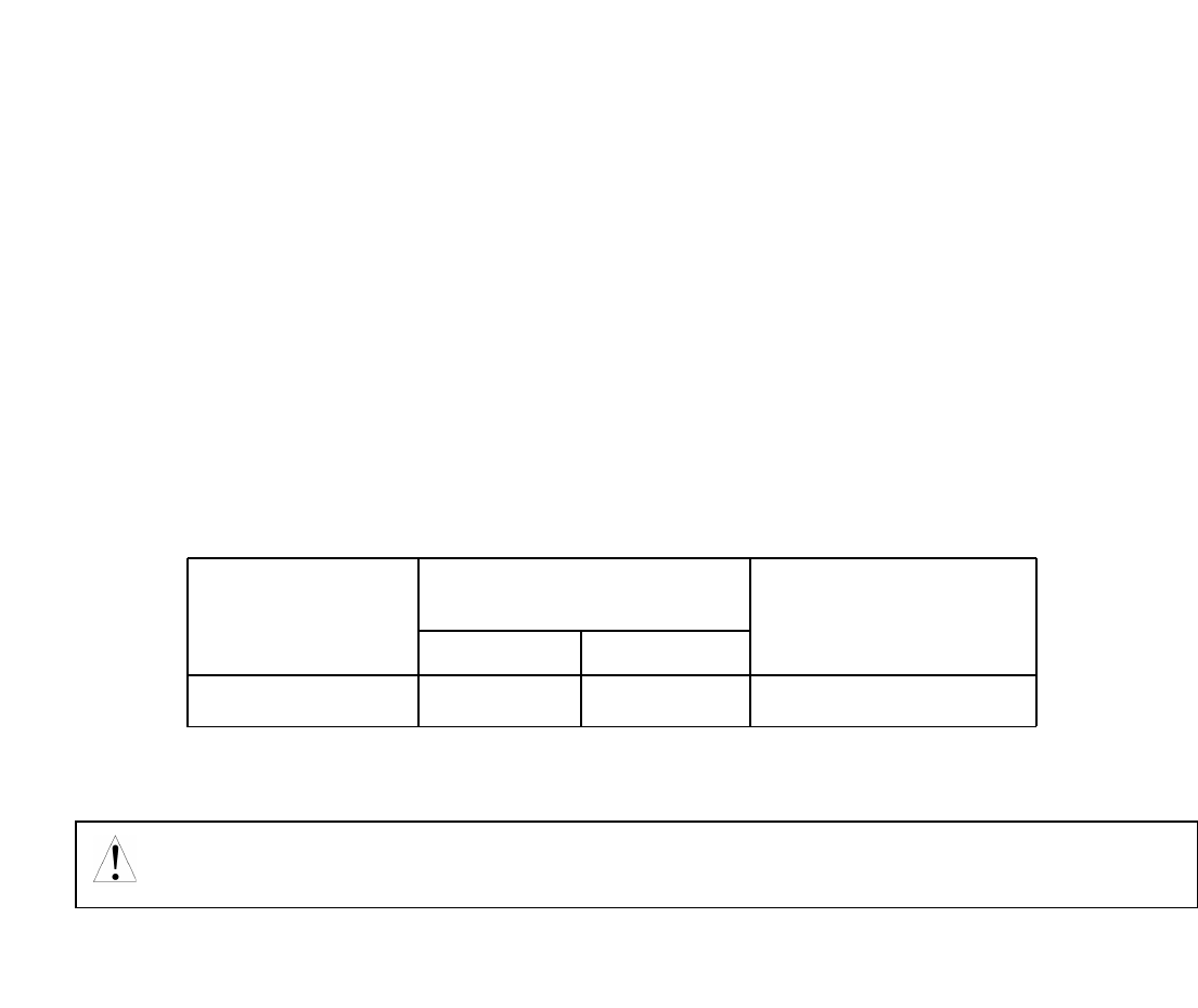
TABLE 2 – TERMINAL BLOCK WIRING INFORMATION
III. CONNECTIONS TO THE SIVF
9
Safety Warning! Do not use FWD-STOP-REV contacts as a safety disconnect since
they are not fail-safe. Use only the AC line for this purpose.
Connection
Designation
Supply Wire Gauge
(AWG – Cu)
Minimum Maximum
Maximum
Tightening
Torque (in-lbs)
Logic Connections 24
14
3.5