
User guide


III. MOUNTING.
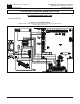
1. Mount the APRM
®
-PC on the 4 bosses located on the inside cover
of the KBPC-240D using the four (4) # 6-32 screws provided.
Position the APRM so that the brake resistor is toward the bottom of
the cover. Be sure not to trap any wires under the APRM mounting
bracket. (See fig. 1.)
2. To mount the FWD-BRK-REV switch in the KBPC first remove the
rubber plug in the FWD-BRK-REV position by unscrewing the retainer
nut on the inside cover. (See fig. 3 p. 5.)
3. Install the FWD-BRK-REV switch assembly into the front cover
making sure the key in the hole lines up with the keyway in the switch
bushing. Be sure the hex nut supplied is installed at the base of the
switch bushing before inserting switch into the KBPC cover.
4. Install the rubber switch boot with integral hex nut over switch lever.
Switch should be in the stop position to facilitate installation. Also,
the switch bushing threads should protrude no more than .25"
(6.4mm) or no less than .10" (2.6mm) through the front cover for
proper installation. Tighten the switch boot so that the bottom seals
against the cover label. Do not overtighten.
FIG. 1 – APRM
®
MOUNTED IN THE KBPC-240D
3
5. FWD-BRK-REV switch remote moun-
ted. It is possible to operate the con-
trol with a remote FWD-BRK-REV
switch or with a remote relay. Care-
fully remove the three switch wires:
S1, S2, S3 from the APRM
®
. Wires
may be extended for remote operation,
but it is suggested that a shielded
cable be used. (See table 1 APRM
®
Operation, p. 2.)
IV. WIRING. Do not wire control
with AC line connected.
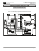
1. Carefully remove from the KBPC main
PC board the 2 jumpers, J8A (con-
nects A1A and A1B) and J8B (con-
nects A2A and A2B). Note: Use long
nose pliers and rock terminal back
and forth to facilitate removal. (See
fig. 2.)
2. Install the wires from the APRM onto
the following terminals on the KBPC
main board. Refer to the internal wiring
diagram provided. (See fig. 5, p. 6.)
FIG. 2 – KBPC-240D JUMPER REMOVAL
4