
Cut Sheet

*Factory calibrated for 0-5 Volts DC signal input.
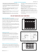
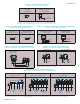
FIGURE 19 – VOLTAGE FOLLOWING
SIGNAL INPUT CONNECTION
(J1 Set to “VOLT” Position)
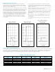
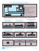
FIGURE 22 – BIDIRECTIONAL (WIGWAG)
MAIN SPEED POTENTIOMETER CONNECTION
(J1 Set to “VOLT” Position)
FIGURE 25 – RUN/FAULT RELAY
CONNECTION (TB1) FIGURE 26 – RUN/FAULT RELAY OUTPUT CONTACT SELECTION (J2)
FIGURE 23 – FORM “C” CONTACT OR RELAY
FORWARD-STOP-REVERSE CONNECTION
FIGURE 24 – OPEN COLLECTOR
FORWARD-STOP-REVERSE CONNECTION
FIGURE 20 – CURRENT FOLLOWING
SIGNAL INPUT CONNECTION
(J1 Set to “CUR” Position)
FIGURE 21 – MAIN SPEED POTENTIOMETER &
FORWARD-STOP-REVERSE SWITCH
CONNECTIONS
(J1 Set to “VOLT” Position)
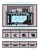
NDBM DBM
J5
TB1
PWR
+5V 0V-5V
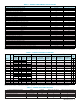
Used to connect the Signal Isolator and Run/Fault Relay to the KBVF.
Sets the drive for operation with the optional Dynamic Brake Module.
Sets the drive for operation with a voltage or current input signal.
Signal Input, Direction Switch, and Main Speed Potentiometer connections.
A
ll jumpers and trimpots are shown in factory set positions.
S
ets the Run/Fault Relay Output Contacts for normally open or closed operation.
Sets the operation of the Run/Fault Relay to Run or Fault.
J
4
C
ON1
R
un/Fault Relay Output Contacts connection.
Signal Offset adjustment trimpot.
Maximum Speed adjustment trimpot.
RUNFAULT
K2REVFWD SIG1 COM1
OFFSET MAX
TB2
K1
CUR
NC
J1
VOLT
J2
NO
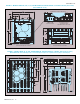
CONNECTION DIAGRAMS FOR SIVFR – SIGNAL ISOLATOR & RUN/FAULT RELAY
Jumper
-5V+5V 0V
TB1
SIG1FWD REV COM1
0 - 2.5 thru 0 - 25 *
Volts DC
-
+
V
J1
VOLTCUR
+5V -5V
TB1
SIG1FWD0V REV COM1
4 - 20 mA DC
Jumper
+
-
J1
VOLTCUR
Forward
0V-5V+5V
TB1
SIG1FWD REV COM1
Main Speed Potentiometer
Stop
Reverse
J1
VOLTCUR
JumperJumper
-5V+5V
TB1
SIG1FWD0V REV COM1
Main Speed Potentiometer
J1
VOLTCUR
0V
Forward
TB1
+5V -5V SIG1FWD REV COM1
Reverse
TB1
+5V -5V
ReverseForward
SIG1FWD0V REV COM1
TB2
Run/Fault Relay Output Contacts
K1 K2
Run/Fault Relay Set for Normally Open Contacts
(F
actor
y Setting)
(Jumper Installed in
“NO”
P
osition)
Run/Fault Relay Set for
Nor
mally Closed Contacts
(Jumper Installed in
“NC”
P
osition)
NC NO
J2
NC NO
J2
FIGURE 18 - SIGNAL ISOLATOR & RUN/FAULT RELAY CONTROL LAYOUT
(
Standard on Models KBVF-45, 48 and optional on other models)
(A42092) – Rev. D – 8/2006
Print Code
KB ELECTRONICS, INC.
12095 NW 39th Street, Coral Springs, FL 33065-2516 • (954) 346-4900 • FAX (954) 346-3377
Outside Florida Call Toll Free (800) 221-6570 • info@kbelectronics.com
www.kbelectronics.com