
Cut Sheet

D
ATA SHEET D-800B
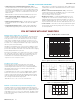
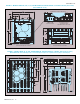
FIGURE 12 – AUTOMATIC-MANUAL START/RESET
(CONN1 is located on the Lower PC Board)
A
utomatic Start Operation
(
Factory Setting)
(
Jumper Installed)
M
anual Start - Reset Operation*
(
Connector Installed)
CON1
A/M
(Momentary Contact)
Red
Black
CON1
Push to Run
FIGURE 13 – FORWARD/REVERSE SPEED SELECTION
(CON2 is located on the Lower PC Board)
Forward Speed Operation
(
Factory Setting)
(
Jumper Installed in “F” Position)
R
everse Speed Operation
(
Jumper Installed in “R” Position)
CON2
F - S - R
CON2
F - S - R
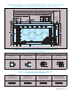
FIGURE 14 – FORWARD-STOP-REVERSE & ENABLE SWITCH CONNECTIONS*
(CON2 is located on the Lower PC Board)
Forward-Stop-Reverse Operation
(Connector Installed)
Forward Enable Operation
(Connector Installed)
Reverse
Forward
Black
White
CON2
Red
Stop
(Close to Run)
(Open to Stop)
White
Black
CON2
*T
he drive can be factory programmed for Run/Stop operation with momentary contacts.
N
otes: 1.
I
n Automatic Mode, the drive
will automatically start when power is applied and a run command is given. The drive will automatically restart after a recovered
f
ault, except for an I
2
t
trip.
2
.
T
he Manual Start Mode is used to start the drive or restart the drive (reset) if a fault has occurred.
*
The drive can be prog
rammed fo
r momentar
y contact operation.
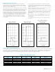
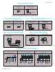
FIGURE 15 – MAIN SPEED POTENTIOMETER CONNECTION
(Terminals P1, P2 & P3 are located on the Lower PC Board)
Wiper
Low
High
P1
(Supplied) (Front View)
Main Speed Potentiometer
P3P2
FIGURE 16 – VOLTAGE FOLLOWING CONNECTIONS*
(Terminals P1 & P2 are located on the Lower PC Board)
0 - 5 Volts DC (Isolated)
0 - 10 Volts DC (Isolated)
P1
+
0 - 5
Volts DC
-
P2 P3
10k
10k
P1 P2 P3
+
0 - 10
Volts DC
-
*If a non-isola
ted signal is used,
install the SIVFR - Signal Isola
tor (Part No.
9597).
(Do not Earth ground signal wiring.)
Note: Models KBVF-45, 48 contain built-in SIVFR - Signal Isolator.
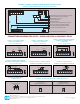
FIGURE 17 - MOTOR & AC LINE INPUT CONNECTIONS
(Motor and AC Line T
erminals ar
e located on the Upper PC Boar
d)
Models KBVF-21D, 22D, 13, 23, 23D, 14, 24, 24D, 26D
(Single Phase AC Line Input)
Model KBVF-27
(Single-Phase and 3-Phase AC Line Input)
Models KBVF-29, 45, 48
(3-Phase AC Line Input)
Ground (Earth)
Chassis
Motor
Single-Phase, 50/60 Hz
AC Line Input
115, 208/230 Volt
*
**
U V
MOTOR
W
AC LINE
L1 L2
3-Phase Connection (L1, L2 & L3)
208/230 VAC - 50/60 Hz
Ground (Earth)
Chassis
Motor
AC Line Input
Single-Phase Connection
Use L1 & L2
MOTOR
VTB1 U W
L1 L2
AC LINE
L3
208/230, 400/460 Volt
3-Phase, 50/60 Hz
Ground (Earth)
Chassis
Motor
*
AC Line Input
MOTOR
V
TB1 U W
L1 L2
AC LINE
L3
*Models KBVF-13, 14: 115 Volt AC line input only. Models KBVF-23, 24, 27, 29: 208/230 Volt AC line input only. Models KBVF-21D, 22D, 23D, 24D, 26D: 115 Volt AC Line Input (with Jumper J1 set to “115V” position) and
208/230
V
olt
AC line input (with Jumper J1 set to
“230V” position).
Models KBVF-45,
48:
400/460
V
olt
AC line input onl
y.
** Model KBVF-21D,
due to its plastic case design,
does not contain a g
round screw
.
7
KB Electr
onics, Inc.