
Cut Sheet

Eliminate Harmful Inrush Current
Most KBVF drives contain an Electronic Inrush Current Limit (EICL™)
circuit.* The EICL™ prevents high AC inrush current each time power is
applied to the drive. The EICL™ feature also allows the drive to be rapidly
switched “on” and “off” with the AC line.
Some competitive drives only use a thermistor type of inrush current limiter
(ICL). The thermistor operates favorably when the drive is initially connected
to the AC line. The problem with the thermistor occurs when the drive is
disconnected from the AC line for a short period of time (1/2 - 2 minutes).
During this time, the main bus capacitors discharge. However, the thermis-
tor takes more than 3 minutes to cool down to the point where its resist-
ance increases enough to limit inrush current. If the drive is reconnected to
the AC line before the thermistor has cooled, very high inrush current
results, which can damage the drive’s power bridge or can weld the
contacts of the AC line switch. In many cases, the main circuit breaker
or fuse will trip.
It could be suggested to leave the drive on continuously to avoid the
restart problem. This philosophy does not work, since the drive could
shut down due to momentary power outages or an operator inadvertently
turning it off and then on.
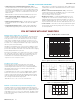
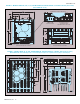
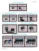
Figure 4 shows the current surge of a drive using a thermistor ICL when
started for the first time. The current surge is normal.
Figure 5 shows the current surge of a drive using a thermistor ICL after the
drive is restarted after a 1 minute shutdown. The current surge is abnor-
mally high and can damage the drive’s power bridge and trip the main
circuit breaker.
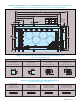
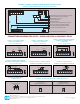
Figure 6 shows the current surge of the KBVF drive using EICL™. The
current surge is normal whether the drive is started for the first time or
restarted anytime.
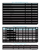
Status Indicators Save Installation Time
The drive contains two diagnostic LEDs. The “ST” LED is a tricolor LED which provides indication of a fault or abnormal condition. The information provided
can be used to diagnose an installation problem such as incorrect input voltage, overload condition, and drive output miswiring. It also provides a signal
which informs the user that all drive and microprocessor operating parameters are normal. When the AC line is applied to the drive, the “PWR” LED
provides an indication of the presence of bus voltage and the proper operation of the logic power supply. See Table 4.
LED Function
State
1
LED Color
LED Color After Recovered Fault
(Manual Start)
ST (Sta
tus)
Normal Opera
tion
Slo
w Flash
Green —
ST (Status) CL (Current Limit) Steady Red
Green
2
ST (Sta
tus)
I
2
t Quick Flash Red
Green
2
ST (Sta
tus)
Short Circuit Slo
w Flash
Red —
ST (Status) Undervoltage Quick Flash Red/Yellow Red/Yellow/Green
ST (Sta
tus)
Over
volta
ge
Slo
w Flash
Red/Y
ello
w
Red/Y
ello
w/Green
ST (Status) Stop Steady Yellow
Green
2
PWR (Power) Bus and Logic Power Supply Steady Green —
Notes: 1. Slow Flash = 1 second on and 1 second off. Quick Flash = 0.25 second on and 0.25 second off. 2. Slow flashing green.
TABLE 4 – LED STATUS INDICATORS
F
igure 4 – Drive with ICL
started for the first time
F
igure 5 – Drive with ICL
r
estarted after 1 minute
Figure 6 – KBVF Drive with EICL™
s
tarted for the first time or
restarted anytime
4
KB Electr
onics, Inc.
*
Because Models KBVF-21D, 22D operate with low levels of AC line current, they contain an ICL
in lieu of EICL™.