
Cut Sheet

D
ATA SHEET D-800B
AC Motors Last Longer
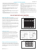
AC drives pr
oduce very fast rising voltages that can be harmful
to motor windings. Some motor manufacturers are now using spike
resistant magnet wire that reduces the chance of insulation breakdown.
Unfortunately, many motors do not contain the spike resistant wire,
especially motors below 1HP.
T
o substantially r
educe the chance of motor winding damage, all KBVF
inverters from 1/10 thru 1.5 HP contain built-in Motor Filters.* Figure 2
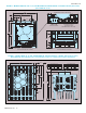
compares a typical inverter waveform with and without the motor filter.It
can be observed that the waveform with the Motor Filter has a r
educed
rate of voltage rise and r
educed voltage spikes.
*Models KBVF-21D, 22D, 13, 23, 23D, 14, 24, 24D, 26D contain the Motor Filter.
160150140130120110
0.1
1
10
100
1
000
Trip Time (Minutes)
Motor Current (%)
CL (Factory Setting)
∞
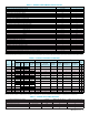
Figure 1 – Modified I
2
t Time vs. Motor Current
Load Regulation (Speed Change)
(0 – Full Load (% Base Speed))
Motor Speed (%)
3
2
1
0 20 40 60 80 100
Figure 3 – Load Regulation vs. Motor Speed
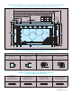
Figure 2 – Typical 3-Phase Inverter PWM Waveforms (230 Volt AC Line)
Waveform without Motor Filter Waveform with Motor Filter
Maintain Constant Motor Speed Under Varying Loads
The KBVF’s unique microcontroller programming, with Static Auto-Tune
and an active motor current algorithm with Boost, is used to stabilize motor
speed. This feature activates each time the AC line is applied. Base speed
load regulation is up to 2.5% over a 30:1 speed range. The KBVF contains
a Slip Compensation Trimpot (COMP), which is factory calibrated for most
motors. See Figure 3.
3
KB Electr
onics, Inc.
• SIVFR Signal Isolator and Run/Fault Relay (Part No. 9597) —
Provides isolation between a non-isolated signal voltage source and the
drive. Run/Fault Relay Output Contacts are also provided, which can be
used to turn on or off equipment or to signal a warning if the drive is put
into the Stop Mode or a fault has occurred. Mounts on the side of the
KBVF heat sink.
N
ote:
M
odels KBVF-45, 48 contain built-in Signal Isolator and Run/Fault Relay Output Contacts.
• DBVF - Dynamic Brake Module (Part No. 9598) — Provides up to
25% continuous braking and 200% instantaneous braking torque
(maximum 1 HP (.75 kW)).
• Multi-Speed Board (Part No. 9503) — Provides multi-speed operation
using external contacts or a PLC. Mounts on the side of the KBVF
heat sink.
• Programming Kit (Part No. 9582) — Includes DownLoad Module™
(DLM) handheld programming device which uploads and downloads
drive programs, PC to DLM serial communication cable, DLM to inverter
communication cable, and PC Windows® based Drive-Link™ communi-
cation software.
• Modbus Communication Module (Part No. 9568) — Allows direct
communication between drive and Modbus* protocol. If a USB commu-
nication cable is required, purchase Part No. 19008.
*O
ther protocols available, contact the Sales Department.
• RFI Filters and Chokes — Provide RFI and EMI Suppression. They
comply with CE Council Directive 39/336/EEC relating to the Class A
Industrial Standard and Class B Residential Standard. These filters are
available for Models KBVF-21D, 22D, 13, 23, 23D, 14, 24, 24D, 26D, 27
only. See RFI Filters and Chokes Selection Guide Publication No. D-321.
• Custom Software — All models can be factory programmed for applica-
tions that require special switching, timing, and PLC functions. Contact
our Sales Department
OPTIONAL ACCESSORIES & FEATURES
YOU GET MORE WITH KBVF INVERTERS
Eliminate Motor Failure Due to Overload
The KBVF contains modified I
2
t Overload Protection.* Part of this function
consists of a Current Limit (CL) circuit, which limits the drive current to a
factory preset level of 160% of the rated motor current. The CL Trimpot
can be used to recalibrate the drive current from 60% thru 200%. The
circuit provides an overshoot function that allows most motors to develop
more than 200% of starting and breakdown torque. Figure 1 illustrates the
time versus motor current relationship.
Standard I
2
t is undesirable because it causes nuisance tripping. It allows a
very high motor current to develop and will turn the drive off after a short
period of time. KB’s RMS Current Limit Circuit avoids this nuisance tripping
while providing maximum motor protection.
If the motor is overloaded to 120% of full load (or 75% of the CL setting),
the I
2
t timer starts. If the motor continues to be overloaded at the 120%
level, the timer will shut down the drive after 30 minutes. If the motor is
overloaded to 160% of full load, the drive will trip in 6 seconds.
*UL approved as an electronic overload protector for motors.