
Cut Sheet

D
escription
S
pecification
F
actory Setting
115 Volt AC Line Input Voltage Operating Range (Volts AC) 115 (±15%) —
2
08/230 Volt AC Line Input Voltage Operating Range (Volts AC)
2
08 (–15%) / 230 (+15%)
—
400/460 Volt AC Line Input Voltage Operating Range (Volts AC) 380 (–15%) - 460 (+15%) —
M
aximum Load (% Current Overload for 2 Minutes)
1
50
—
C
arrier, Switching Frequency (kHz) 16, 8 —
S
ignal Following Input Voltage Range
1
(
Volts DC)
0 - 5 —
O
utput Frequency Resolution (Bits, Hz) 10, .06 —
Minimum Speed Trimpot (MIN) Range (% Frequency Setting) 0 - 40 0
M
aximum Speed Trimpot (MAX) Range (% Frequency Setting) 70 - 110 100
A
cceleration Trimpot (ACC) and Deceleration Trimpot (DEC/B) Range (Seconds)
.
3 - 20
1
.5
Boost Trimpot (DEC/B) Range (50 Hz Only) (Volts/Hz) 0 - 30 5
S
lip Compensation Trimpot (COMP) Range at Drive Rating (Volts/Hz)
0
- 3
1
.5
C
urrent Limit Trimpot (CL) Range (Amps AC): KBVF-21D .65 - 1.8 1.6
KBVF-22D 1.0 - 2.8 2.4
K
BVF-13, 23, 23D 1.5 - 4.5 3.8
KBVF-14, 24, 24D 2.5 - 7.5 6.4
K
BVF-26D 3.5 - 10.5 8.8
K
BVF-27
4
.0 - 12.5
1
0.7
KBVF-29 5.5 - 17.0 14.4
K
BVF-45
3
.0 - 8.5
7
.4
KBVF-48 5.0 - 15.5 13.3
Motor Frequency Setting (Hz) (Jumper J1) 50, 60 60
O
utput Frequency Multiplier (X1, X2) (Jumper J2)
2
1
,2 1
Minimum Operating Frequency at Motor (Hz) 0.3 —
Speed Range (Ratio) 60:1 —
Speed Regulation (30:1 Speed Range, 0 - Full Load) (% Base Speed)
3
2.5 —
Overload Protector Trip Time for Stalled Motor (Seconds) 6—
A
C Line Input Undervoltage/Overvoltage Trip Points for 115 Volt AC Line (±5%) (Volts AC)
4
76 - 141 —
AC Line Input Undervoltage/Overvoltage Trip Points for 208/230 Volt AC Line (±5%) (Volts AC)
4
151 - 282 —
AC Line Input Undervoltage/Overvoltage Trip Points for 400/460 Volt AC Line (±5%) (Volts AC)
4
302 - 567 —
Run/Fault Relay Output Contact Rating
5
(Amps at 30 Volts DC, 125 Volts AC, 250 Volts AC)
1, 0.5, 0.25 —
Operating Temperature Range (°C) 0 - 45 —
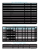
Notes: 1. Models KBVF-45, 48 contain built-in signal isolation. For other models, if a non-isolated signal is used, install the SIVFR - Signal Isolator (Part No. 9597). 2. Allows the motor to operate up to two times the rated RPM.
Constant horsepower will result when operating the drive in the “X2” mode. 3. Dependent on motor performance. 4. Do not operate the drive outside the specified AC line input voltage operating range. 5. Models KBVF-45, 48 only.
Model
Part
No.
AC Line Input Output
Features by Model
4
Net Wt.
Volts AC
(50/60 Hz)
Phase
(
φ)
Maximum
Current
(Amps AC)
Fuse or Circuit
Breaker Rating
(Amps)
Volt Range
(Nominal)
(Volts AC)
Maximum Continuous
Load Current
(RMS Amps/Phase)
Maximum
Horsepower
(HP (kW))
Motor Filter
(See Figure 2)
Signal Isolator and
Run/Fault Relay
(See Figure 18)
AC Line and
Motor Wiring
(See Figure 17)
lbs kg
KBVF-21D 9581
115 1 4.0
5 0 - 230 1.0 1/10 (.07) S O QD 0.7 0.3
208/230 1 2.5
KBVF-22D 9572
115 1 6.0 10
0 - 230 1.5 1/4 (.18) S O QD 1.3 0.6
208/230 1 3.8 5
KBVF-13 9957 115 1 11.0 15 0 - 230 2.4 1/2 (.37) S O QD 1.3 0.6
KBVF-23 9958 208/230 1 7.0 10 0 - 230 2.4 1/2 (.37) S O QD 1.3 0.6
KBVF-23D 9959
115 1 11.0 15
0 - 230 2.4 1/2 (.37) S O QD 1.3 0.6
208/230 1 7.0 10
KBVF-14 9977 115 1 16.0 20 0 - 230 4.0 1 (.75) S O QD 2.2 1.0
KBVF-24 9978 208/230 1 10.0 15 0 - 230 4.0 1 (.75) S O QD 2.2 1.0
KBVF-24D 9979
115 1 16.0 20
0 - 230 4.0 1 (.75) S O QD 2.2 1.0
208/230 1 10.0 15
KBVF-26D 9496
115 1 22.0 25
0 - 230 5.5
1
1
⁄2 (1.13)
1
S O QD 2.9 1.3
208/230 1 14.0 15
KBVF-27 9591 208/230
1 17.0 20
0 - 230 6.7 2 (1.5) N O TB 4.1 1.9
3 8.0 10
KBVF-29
2
9593 208/230 3 10.8 15
0 - 230
9.0 3 (2.25) N O TB 4.6 2.1
KBVF-45
3
9590 400/460 3 5.3 10 0 - 400/460 4.6 3 (2.25) N S TB 4.1 1.9
KBVF-48
2,3
9592 400/460 3 9.6 15 0 - 400/460 8.3 5 (3.75) N S TB 4.6 2.1
Notes:
1.
Model KBVF-26D is ra
ted 2 HP (1.5 kW) f
or most premium ef
ficiency motors.
2. Models KBVF-29,
48 contain a built-in cooling fan.
3. Models KBVF-45,
48 are ra
ted 0 - 400
V
olts AC for 50 Hz motor operation and 0 - 460
Volts AC for 60 Hz motor operation.
4. S = Standard Feature, N = Not Available, O = Optional Feature, QD = Quick-Connect Terminals for AC line and motor wiring, TB = Terminal Block for AC line and motor wiring.
TABLE 1 – GENERAL PERFORMANCE SPECIFICATIONS
TABLE 2 – ELECTRICAL RATINGS & FEATURES
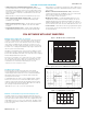
T
ABLE 3 – JUMPER SELECT
ABLE FEA
TURES
Description (bold indicates factor
y setting)
Location Designation KBVF-21D
,
22D
,
23D
,
24D, 26D
KBVF-13,
23,
14,
24,
27,
29,
45, 48
AC Line Input
Voltage (115,
230) Upper PC Board J1 —
Automatic-Manual Start/Reset (A,M) Lower PC Board CON1
F
orward or Reverse Direction (
F,
R)
Lo
wer PC Board
CON2
Motor Frequency (50Hz, 60Hz) Lower PC Board J1
Frequency Multiplier (X1, X2) Lower PC Board J2
2
KB Electr
onics, Inc.