
Users Manual Part 2
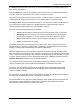

Table Of Contents
- Appendix B. Regulatory Compliance and Agency Approvals
- Chapter 1. Kaye ValProbe RT System
- Chapter 2. Kaye ValProbe RT Hardware
- Chapter 3. ValProbe RT System Connections
- Chapter 4. Creating User Accounts
- Chapter 5. Defining Equipment
- Chapter 6. Defining Assets
- Chapter 7. Defining Study Setups
- Chapter 8. Viewing Live Data
- Chapter 9. Qualification Study
- Chapter 10. Sensor Verification
- Chapter 11. Qualification Reports
- Appendix A. Specifications
- A.1 Kaye ValProbe RT System
- A.1.1 List of Certified Countries
- A.1.2 Regulatory Compliance
- A.1.3 RF System Operating Frequency and Modulation
- A.1.4 RF Channels
- A.1.5 RF Network Topology and PAN ID (Network ID)
- A.1.6 Antenna Diversity
- A.1.7 Data Rate and Data Encryption
- A.1.8 RF Range (Line of Sight and Outdoor)
- A.1.9 Number of Loggers and Sensors Supported
- A.1.10 Sensor Sampling Rate
- A.1.11 Data Transmission Rate
- A.1.12 Sensor Samples Data Storage Capacity
- A.1.13 Optional Extendable Base Station Antenna
- A.2 Kaye ValProbe RT Base Station
- A.2.1 Input Power and Adaptor Ratings
- A.2.2 Installation Category
- A.2.3 Overvoltage Category and Electrical Safety Protection Class
- A.2.4 Input DC Power On/Off Switch
- A.2.5 Front Panel LED Indications and Buzzer
- A.2.6 Bath and IRTD Interface Ports
- A.2.7 USB Port
- A.2.8 Ethernet Communication Port
- A.2.9 Reset Switch to Reload Default Factory Settings
- A.2.10 Wakeup Magnet
- A.2.11 Batteries
- A.2.12 Unit Dimensions
- A.2.13 Enclosure Material
- A.2.14 Environmental Ratings
- A.3 Kaye ValProbe RT Logger
- A.3.1 Installation Category
- A.3.2 Overvoltage Category and Electrical Safety Protection Class
- A.3.3 Magnetic Switch
- A.3.4 LED Indications
- A.3.5 Calibration
- A.3.6 Real Time Clock Accuracy
- A.3.7 Sensing Elements
- A.3.8 Housing Material
- A.3.9 Logger Base Dimensions
- A.3.10 Ingress Protection
- A.3.11 Insulating Canister X2545
- A.3.12 Battery
- A.3.13 Shelf Life
- A.3.14 Battery Life
- A.4.1 Measurement Accuracy
- A.4.2 Body Environmental Ratings:
- A.4.3 Number of Input Channels
- A.4.4 Sensor Types and Measurement Range
- A.4.5 Sensor Lengths
- A.5.1 Measurement Accuracy
- A.5.2 Body Environmental ratings:
- A.5.3 Number of Input Channels
- A.5.4 Sensor Types and Measurement Range
- A.5.5 Sensor Lengths
- A.6.1 Measurement Accuracy
- A.1 Kaye ValProbe RT System
- Appendix B. Regulatory Compliance and Agency Approvals
- B.1 Electrical Safety Approvals:
- B.2 Radio and EMC Certification Approvals:
- B.3 Ingress Protection for Kaye ValProbe RT Logger
- B.4 United States FDA 21 CFR Part 11 Complaint Software Application
- B.5 Transportation Regulations
- B.6 FCC Compliance Statement
- B.7 ISED Canada Compliance Statement
- B.8 EU Compliance Statement:
- B.9
- Product Certification Labels
- Appendix C. Environnemental Compliance
- Appendix D. Warranty and Returns:
- Appendix E. Service Information

Chapter 7: Defining Study Setups
Kaye ValProbe RT User Manual 66
7.6. Assigning Sensors to Groups
Figure 74: Group Sensors Screen
On the Group Sensors screen, Loggers are assigned to groups. The same sensor can be
assigned to multiple groups.
After the configuration of the sensors, the next step is to group them by pressing Group
Sensors. The Group Sensors screen displays a scrollable listing of existing groups, as well as
the New Group button.
As long there is no group defined, the Default Group button automatically generates groups
for sensors with the same measured variable, like temperature and pressure.
To assign sensors to groups:
Select individual sensors to select them for the group. These sensors now appear deep
blue with an orange checkbox.
Press the New Group button, and the Group Name textbox appears on the screen. The
Group Name textbox accepts characters that can be upper and lower case, numeric, special
characters like hyphen, underscore, slashes (forward and backward) and, blanks. Enter a
name and toggle the Save button to save the group.
This screen also offers the following options:
• Delete - permits deletion of a group of sensors
• Move Sensors - permits moving sensors to another sensor group (specified in drop-
down list)
• Customized Header for each group: The group specific header fields, Asset ID
prepopulates from the Asset, and the SOP number field prepopulates from the
Define setup screen. The header can be customized for each group. Any new
information needs to be saved using the Save button before switching to another
group.
• Add Sensors - add further sensors to a group
• A Wiring Overlay – accessible via the Book icon - enables wiring overlay
configuration.