Final Drive ""
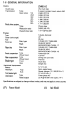
GENERAL Table Torque General Cable, Model Periodic Before Wire, Servicing Identification andSpecifications Maintenance Locking and Hose Agent Chart Routing INFORMATION of Contents ...1-2 ...1-4 ...1-5 ...1- 7 ...1-9 .
1-2 GENERAL INFORMATION Before Servicing Before starting to service a motorcycle. careful reading of the applicable section is recommended to eliminate unnecessary work. Photographs. diagrams. notes. cautions. warnings. and detailed descriptions have been included wherever necessary. Nevertheless. even a detailed account has limitations, a certain amount of basic knowledge is also required for successful work. Especially note the following: (1} Dirt Before removal and disassembly, clean the motorcycle.
GENERAL INFORMATION 1-3 (12) Oil Seal and Grease Seal Replace any oil or grease seals that were removed with new ones, as removal generally damages seals. When pressing in a seal which has manufacturer's marks, press it in with the marks facing out. Seals should be pressed into place using a suitable driver, which contacts evenly with the side of seal, until the face of the seal is even with the end of the hole.
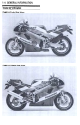
1-4 GENERAL Model INFORMATION Identification ZX400-H2 Left Side View: ZX400-H2 Right Side View:
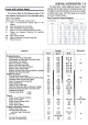
GENERAl INFORMATION 1-5 General Specifications ZX400-H2 Items Dimensions: Overall length Overall width 2035 mm, (I) 2050 705 mm Overall height 1 1 25mm Wheelbase 1 395 mm Road clearance Seat height 120 mm 765 mm mm, 163 kg Dry weight Curb weight: Front Rear 95 kg 94 kg Fuel tank capacity 16.0 L Performance: Braking 1 3.5 m from distance Minimum turning radius 50 km/h 3.2 m Engine: i 4-stroke, DOHC, 4-cylinder I Liquid-cooled I 57.0 x 39.0 mm 398 mL 12.1 45.
1-6 GENERAL INFORMATION Items ZX400-H2 Clutch type Transmission Type Gear 1 st ratios: 2nd 3rd 4th 5th 6th Final drive Wet multi disc 6-speed, constant mesh, return shift 2.846 (37/13) 2.055 (37/18) 1.631 (31/19) 1.380 (29/21) 1.240 (31/25) 1 .111 (30/27) system: Type Reduction Overall ratio drive ratio Chain drive 3.000 ( 45/15) 7.
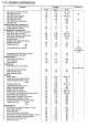
GENERAl Torque and locking Agent The following tables list the tightening torque for the major fasteners requiring use of a non-permanent locking agent or liquid gasket. INFORMATION 1-9 The table below, relating tightening torque to thread diameter, lists the basic torque for the bolts and nuts. Use this table for only the bolts and nuts which do not require a specific torque value. All of the values are for use with dry solvent-cleaned threads.
1-10 GENERAl INFORMATION Fastener Oil Pressure Switch Terminal Oil Pressure Switch Oil Pump Cover Screws Oil Plug (Right, M18) Oil Plug (Left, PT%) Oil Cooler Pipe Fitting Bolt Oil Pan Bolts Engine Removal/Installation: Engine Mounting Bracket Bolt Engine Mounting Bolts Cra n kshaft/T ransm ission : Shift Drum Cam Mounting Bolts Shift Drum Set Lever Bolt Shift Drum Bearing Retainer Bolt Shift Return Spring Bolt Neutral Switch Breather Plate Mating Surfaces Breather Plate Bolt Crankcase Bolts Cl>6 Cl>8 Cr
GENERAl Fastener Side Stand Bracket Bolts Electrical System: Spark Plugs Pickup Coil Cover Bolts Pickup Coil Bolt Timing Rotor Allen Alternator Alternator Cover Alternator Rotor Alternator Stator Alternator Stator Alternator Cover 49 Bolts Bolt Allen Bolt Lead Clamp Bolt Mating Surfaces ft-Ib 5.0 36 23 31 3.2 23 1.3 0.90 113 in-Ib 78 in-Ib 0.65 2.5 56 in-Ib 18.0 0.90 8.0 0.85 0.85 73 in-Ib 58 74 in-Ib 74 in-Ib 9.8 13 8.8 6.4 Bolts kg-m 4.0 2.6 1.0 2.3 39 25 25 8.8 78 8.3 8.3 29 19.
1-12 GENERAL INFORMATION Cable. Wire. and Hose Routing Run the cable into the clamp. 1. Clutch Cable 2. Choke Cable 3. Throttle Cable 4.
~ GENERAL INFORMATION 1-13 1. Battery Vent Hose Battery Fuel (Transparent) 2. Battery Vent Hose (Black) 3. Fuel Tank Breather Hose 4. Coolant Reservoir Tank Breather Hose Tank / / 0-.. / @ ~ ~-L/ /~~ /f"- Rear Fender Coolant Reservoir Tank ..::;..,.I , (front) Joint .-~ ~~ Run the the 'A ~ under pipe. ( ~ ~ cross horse >~Iamp /1\- .;,~;,;'" " ,,' , .~...
1-14 GENERAL INFORMATION View Looking at Front 1 .Main Harness 2. To Right Grip Switch 3. To Left Grip Switch 4. To Water 5. Starter Temperature Motor Sensor lead 10. To Oil Pressure Switch, Neutral Switch and Side Stand Switch 11. Alternator Lead 12. Battery ( + ) Lead 13. Rear Harness 6. 7. 8. 9.
GENERAL INFORMATION 1-15 Run the lead over the fairing stay. @ 1.ToHorn 2. Ignition Switch Lead 3. To Ignition Coil 4. To Radiator Fan 5. Water Temperature Sensor 6. Ground Lead 7. To Left Turn Signal Light 8. Radiator Fan Switch Lead 11. Fuel Pump Lead 12. Pickup Coil Lead 13. Rear Brake Light Switch Lead 9. Main Harness 10.
1-16 GENERAL INFORMATION To Main Harness Run the lead inside of the ~ water - 1 f "'"--' pump. 1 , - 0)- t m ~v )~ ~ 1. Alternator ]1 Lead 2. To Oil Pressure Switch 3. To Neutral Switch 4. Side Stand Switch 5.
FUEL SYSTEM Table Specifications Special Exploded Throttle Surge Choke Air Carburetors Fuel Fuel Tools Throttle Choke Tank Cable Surge Air Oil Service Element Carburetor Idle Cleaner Carburetor Installation Removal Fuel Removal Installation View Grip Cleaner Draining Speed Tank Pump Tank Cable , Cable and Fuel Cleaning and Pump Filter of AdjustmentAdjustment Cables Adjustment Installation Removal Disassembly Housing RemovaJ Level Inspection InspectionInspection Filter , Ad
2-2 FUEL Exploded SYSTEM View
2-4 FUEL SYSTEM Specifications Item Throttle Standard Grip Free Play 2 -3mm Choke Cable Free Play 2 -3mm Idle Speed 1 200 Carburetor :t 50 r/min (rpm) Specifications: Make/type Synchronization vacuum Main jet Standard Option Main air jet Needle jet Jet needle mark Pilot jet (slow jet) Pilot air jet Pilot screw Starter jet Service fuel level Float height Keihin/CVK-D32 2.
FUEL SYSTEM Throttle Grip and Cables Throttle Cable .Check throttle Adjustment grip free play. Grip Free Play Standard: *If .Tighten Accelerator B. Adjuster grip opened. mm the free play is incorrect, loosen the locknut and turn the adjuster of the accelerator cable until the proper amount of throttle grip play is obtained. A. Locknut *If 2 -3 A. Cable Co Locknut Do Decelerator Cable .
2-6 FUEL SYSTEM Choke Cable Surge Tank Choke Cable Adjustment .Remove surge tank (see this chapter). .Check choke cable free play. O Remove the fuel tank (see Fuel Tank Removal). O Determine the amount of choke cable play at the choke lever. Pull the choke lever until the starter plunger lever at the carburetor contacts with the starter plunger; the amount of choke lever lower end travel is the amount of choke cable play. Surge Tank Removal .Remove the fuel tank (this chapter). .
FUEL SYSTEM Air Cleaner Element Cleaning .Remove the surge tank (see this chapter). .Take out the air cleaner element. A. Air B. Plug Cleaner .Remove Housing Drain Hose Removal the following. Fuel Tank (see Fuel Tank Removal) Serge Tank Air Cleaner Crankcase .Remove A. Air Cleaner Element B. Element Element Breather the air cleaner (see Element Cleaning) Hose housing. Mesh .
2-8 FUEL SYSTEM .Check Carburetors OTurn the fuel level as shown. out the carburetor drain until the fuel level in the gauge Idle Speed Adjustment .Start the engine and warm it up thoroughly. .Turn the handlebar from side to side while idling the engine. idle speed varies, the throttle cables may be poorly routed or they may be damaged. .Correct any problem before operating the motorcycle. *If .Check idle plug a few turns. Wait settles.
FUEL SYSTEM ~ 2-9 / Carburetor Disassembly / Assembly ~ Float Height Standard: 11 :t2 mm NOTE 0 Do not push the needle rod in during the float height measurement. Carburetor Removal CD .Remove the following. Fuel Tank (see Fuel Tank Removal) Surge Tank (see Surge Tank Removal) Air Cleaner Housing (see Air Cleaner Removal) Idle Adjuster Fuel Hoses .Loosen the carburetor carburetors. Carburetor .
2-10 FUEL SYSTEM .Turn the throttle cable lever to check that the throttle butterfly valves move smoothly and return by spring tension. * If the throttle valves do not move smoothly. Replace the carburetors. .Check that the O-rings on the float bowl and pilot screws and the diaphragm on the vacuum piston are in good condition. * If any of the O-rings or diaphragms are not in good condition, replace them. .Check the plastic tip of the float valve needle.
FUEL SYSTEM Installation Fuel Tank .Install Removal .Turn the fuel tap to the OFF position to stop the fuel flow. .Remove the following. Front Seat (see Frame chapter) Side Cover Assembly Fuel Tank Mounting Bolts Fuel Tap with Fuel Hoses left installed and Fuel Hose to the carburetor removed Air Duct Clamp A. Mounting Bolts B. Fuel Tap NOTE 0 To take the air ducts out, remove the duct pawls from the inside of the fuel tank. .Remove the fuel tank. the fuel tank hoses.
COOLING Table Specifications Exploded View Special Sealant Coolant Coolant Water Coolant Water Pressure Installation Removal Radiator Pump Pump and Radiator Removal Radiator Thermostat ToolFlow Inspection Installation Removal ,' Level Chart Draining Filling Testing Inspection Inspection , .. Radiator Inspection Cap Fan Inspection .. . , SYSTEM of Contents ..3-2 ..3-3 ..3-3 ..3-3 ..3-4 ..3-5 ..3-5 ..3-5 ..3-5 ..3-6 ..3-7 ...3-7 ...3-7 ...3-7 ...3-8 ...3-8 ...3-8 ...3-9 .
3-2 COOLING Exploded SYSTEM View ~tJ' c:::::;,~ ~ , "'@ @) @ >@ CD "" T1 T2 T3 T4 T5 l " "' "' : 2.0 N-m (0.2 kg-m. 17 in-Ib) : 3.4 N-m (0.35 kg-m. 30 in-Ib) : 7.8 N-m (0.8 kg-m. 69 in-Ib) : 8.8 N-m (0.9 kg-m. 78 in-Ib) : 18 N-m (1.8 kg-m.13 ft-Ib) : Apply a non-permanent threads. SS: Apply silicone sealant locking agent to the to the threads.
~ COOLING SYSTEM Specifications Standard Items Coolant: Type Color Mixed ratio Freezing point Total amount Permanent type of antifreeze for aluminum engines and radiators Green Soft water 50%, coolant 50% -35°C ( -31°F) 2.3 L (reservoir tank full level) Radiator: Cap relief pressure Thermostat: Valve opening temperature Valve full opening lift Special Tool Socket Wrench, Hex 8: 57001 -1 268 93 -123 kPa (0.95 -1 .25 kg/cm2, 14 -18 80.0 -84.
3-4 COOLING Coolant SYSTEM Flow Chart When the engine is cold, the thermostat is closed so that the coolant flow is restricted through the small hole (air hole) on the thermostat, causing the engine to warm up more quickly.
COOLING .Remove Coolant .Place SYSTEM 3-5 the fairings. a container .Remove under the engine. the drain plug. Coolant Level Inspection NOTE OCheck the level when the engine is cold ambient temperature). (room or .Check the coolant level in the reservoir tank with the motorcycle held perpendicularly. .Check the coolant level from between the fuel tank and the flame at the left side. * If the coolant level is lower than the lower level line, add coolant to the upper level line. A. Water Pump B.
3-6 COOLING SYSTEM Pressure .Remove pressure T esting the radiator cap, and tester on the radiator install a cooling system filler neck. NOTE 0 Wet the cap sealing surfaces with water or coolant to prevent pressure leaks. .Build up pressure in the system carefully until pressure reaches 123 kPa (1.25 kg/cm2, 18 psi). A. Radiator B. Filler Neck o Fill the reservoir tank up to the upper level line with coolant. .Watch the gauge for at least 6 seconds.
COOLING Water plug. .Remove the following. Shift Lever Engine Sprocket Cover Radiator Hose Clamp on Water Pump Water Pipe Water Pump Mounting Bolts(2) Water .Pull B. Pump the radiator water 3-7 Water Pump Pipe Mounting Bolt Radiator Hose Clamp Bolt .Apply a non-permanent locking agent to the engine sprocket cover bolt (one bolt only -see Final Drive Pump Removal .Remove the fairings. .Drain the coolant by removing the water pump drain A.
3-8 COOliNG Radiator SYSTEM and Radiator Fan Removal The radiator fan is connected directly to the battery. The radiator fan may start even if the ignition switch is off. NEVER TOUCH THE RADIATOR FAN UNTIL THE RADIATOR FAN CONNECTOR IS DISCONNECTED. TOUCHING THE FAN BEFORE THE CONNECTOR IS DISCONNECTED COULD CAUSE INJURY FROM THE FAN BLADES. .Remove the following. A.
COOLING 1. Steam Gun Running 1. Direction Radiator Cap Inspection .Check the condition of the top and bottom valve seals of the radiator cap. * If anyone of them shows visible damage, replace the cap. Pressure Tester .Install Valve Valve 3. Valve Spring Seal Seal the cap on a cooling system pressure tester. NOTE 0 Wet the cap sealing surfaces with water or coolant to prevent pressure leakage. Cap Radiator Cap Relief Pressure *If 1 .Bottom Radiator 3-9 .
3-10 COOLING SYSTEM Thermostat Removal .Remove the fairing and the side cover assembly. .Drain coolant (cylinder head, cylinder). .Remove the following. Carburetor (see Fuel System chapter) Hose (Thermostat Housing) Mounting Bolts Water Temperature Sensor Connector .Remove the thermostat housir,g on the cylinder. .Remove the thermostat from the housing. 1 .Thermostat *If 2. Thermometer the measurement is out of the specified the thermostat. Thermostat 80 -84°C A. Housing B.
ENGINE Table Exploded View , , 4-2 Specifications 4-4 Special Tools 4-6 Sealant , 4- 7 Cylinder Head Cover 4-8 Removal 4-8 Installation 4-8 Camshaft Chain Tensioner 4-9 Removal 4-9 Installation 4-9 Camshaft 4-10 Camshaft Removal 4-10 Camshaft Installation 4-11 Camshaft, Camshaft Cap Wear 4-12 Camshaft Chain Wear 4-12 Rocker Arm, Rocker Shaft 4-13 Rocker Arm and Rocker Shaft Removal 4-13 Rocker Arm and Rocker Shaft Installation Notes 4-13 Rocker Arm and Rocker Shaft Inspection Note 4-13 Cylinder Head 4-14
ENGINE TOP END 4-3 @ ~ ~r c .~ " ., :" ~" ~" ~ ~ ~ ~ ~ , @ 0 \\ ~c:::c ~ ""' ,~ e ~ ~ ~ B ~ 0 ~ >@ ~ \ ~\ ~ ~ ~ I @ ~-~ \ e "'~ P" --, p. ~ , ~ I ~ ! ~ ) ~oq;;::::: ,~ mil' J@ @ e ~ t ~ 1 ~ A / ~ / ~ '@ /\ CD T1: T2: T3: T4: L: , 8.8 N-m (0.9 kg-m. 78 in-Ib) 9.8 N-m (1.0 kg-m. 7.0 ft-Ib) 12 N-m (1.2 kg-m. 8.5 ft-Ib) 25 N-m (2.5 kg-m. 18.0 ft-Ib) Apply a non-permanent locking agent to the threads. M: Apply molybdenum disulfide grease.
~ 4-4 ENGINE TOP END Specifications Item Standard Service Limit Camshaft: Cam height Camshaft, Inlet 31 .778 -31 Exhaust 31.469 camshaft B journal diameter: A B Camshaft bearing Camshaft runout Camshaft chain Cylinder 31 .68 mm mm 31 .37 mm cap clearance A Camshaft .918 mm -31.609 inside diameter 0.028 -0.071 mm 0.0780.121 mm 23.950 -23.972 mm 23.900 -23.922 mm 24.000 -24.021 mm 0.16 mm 0.21 mm 23.92 mm 24.08 mm 0.1 20-link 127.0- length 127.4 mm mm 23.
ENGINE Item Standard TOP END Service Limit Valve/valve guide clearance (wobble method): Inlet Exhaust 0.031 -0.140 mm 0.0850.180 mm 0.34 mm 0.41 mm 3.975 -3.990 3.955 -3.970 4.000 -4.012 3.96 mm 3.94 mm 4.08 mm mm 57.10 mm mm 56.79 mm Valve stem diameter Inlet Exhaust Valve guide inside diameter Cylinder. Cylinder mm mm mm Piston: inside diameter ~ 57.000 Piston diameter Piston/cylinder clearance 56.942 2 -56.957 0.043 -0.070 + 0.5 mm 0.030 -0.
4-6 ENGINE TOP END Special Tools Compression Gauge: 57001 -221 Compression Gauge Adapter, M10 X 1.0: 57001-1317 Rocker Arm Holder: 57001 -1270 Valve Guide Reamer, 4: 57001-1274 Valve Spring Compressor Assembly: Valve Spring Compressor Adapter, 57001-241 <1>21: 57001-1272 Valve Seat Cutter Holder, 4: 57001-1275 Valve Seat Cutter, 45° -4>24.
ENGINE Valve Seat Cutter, 3L -25: 57001-1118 Valve Seat Cutter, 60. -30: 57001-1123 Sealant Valve Seat Cutter, 32.
4-8 ENGINE TOP END Cylinder Head Cover Removal .Remove the following. Fuel Tank (see Fuel System chapter) Air Cleaner Housing (see Fuel System chapter) Ignition Coils Throttle Cable Choke Cable Baffle Plate 1. A. Baffle .Remove cover. A. Bolts Plate Bolt the cylinder head cover bolts and take off the B. Cylinder Head Cover I nsta!lation .Replace the head cover gasket with new one if it is damaged. .Apply silicone sealant to the cylinder head as shown. .
ENGINE Camshaft TOP END 4-9 Chain Tensioner Removal .Remove .Remove the pickup coil cover. the mounting bolts and take off the camshaft chain tensioner. A. Taper Part (Stopper) B. Push Rod .Compressing the spring against the push rod head, insert a thin wire through the hole in the push rod to keep the spring in place. A. Camshaft Chain B. Mounting Bolts .Pull Tensioner c. Lock out the rod from the cam chain guide Bolt (rear side) A. Wire B. O-ring .Apply .
4-10 ENGINE TOP END OApply silicone sealant to the crankcase parting line and grommet (see 4-12). OApplya non-permanent (see 4-12). Camshaft locking agent to only one bolt Camshaft Removal .Remove the following. Lower Fairings (see Frame chapter) Pickup Coil Cover Damper Rubber (from Rear Cam Chain Guide) .Remove the following.
ENGINE TOP END 4-11 .Pull the tension side (exhaust side) of the chain taut to install the chain. OThe timing marks must be aligned with the cylinder head upper surface and positioned respectively as shown, after the camshaft chain slack is taken up by the tensioner. Camshaft Installation .Installation is the reverse of removal. Note the follow- ing. .Apply engine oil to all cam parts.
4-12 ENGINE TOP END NOTE 0 Do not turn the camshaft when the plastigage between the journal and camshaft cap. *If any clearance diameter exceeds of each camshaft the service journal limit, with measure is the a micrometer. Camshaft. Camshaft Cap Clearance #1. #4 Journals Standard: Service limit: #2. #3 Journals Standard: Service limit: A. Apply silicone sealant. .Apply a non-permanent locking agent to the following bolt only. 0.028 -0.071 0.16 mm mm 0.078- 0.121 mm 0.
ENGINE I Rocker Arm, Rocker Shaft TOP END 4-13 ~ Rocker Arm and Rocker Shaft Removal .Remove the camshafts(this chapter). I -L&-
4-14 ENGINE Cylinder TOP END Removal .Drain coolant (see Cooling System chapter) .Remove the following. Radiator (see Cooling System chapter) Muffler Camshafts (see this chapter) Oil Hose (Cylinder Head) Engine Mounting Bracket Bolts, Nuts (Cylinder Head) .Remove the cylinder head bolts and take off the cylinder head. Head Cylinder CompressionMeasurement NOTE 0 Use the battery which is fully charged. .Warm up the engine thoroughly. .Remove the following.
ENGINE TOP END 4-15 Valves Valve Clearance Adjustment NOTE 0 Valve clearance must be checked and adjusted when the engine is cold (at room temperature). .Remove the following. Cylinder Head Cover Spark Plug Retainer .Using a thickness gauge, measure the valve clearance between the rocker arm and the cam.
4-16 ENGINE TOP END .Apply engine oil to the O-ring, retainer. install the spark plug *If the valve clearance is not within the specified range, first record the clearance, and then adjust it. .To change the valve clearance, replace the shim with one of a different thickness. NOTE 0 Mark and record shim locations reinstalled in their original positions. so they can be .To select a new shim which brings the valve clearance within the specified range.
ENGINE 1. Valve Guide Reamer: TOP 1 .Good 2. 3. Too narrow 4. Uneven Too END 4-17 wide 57001-1274 Valve Seat Outside Diameter .If the outside diameter of the seating pattern on the valve seat is too large or too small, repair the valve seat. Valve Seat Outside Standard: Diameter Inlet : Exhaust : 21.5 ~ 21.7 mm 18.5 ~ 18.7 mm Valve Seat Repair {Valve Lapping) .Using the valve seat cutters (special Valve Seat Width Inspection .Check the valve seat width.
4-18 ENGINE TOP END NOTE ODo not use a wire brush to remove the metal particles from the cutter. It will take off the diamond particles. 4. Setting the valve seat cutter holder in position, operate the cutter in one hand. Do not apply too much force to the diamond portion. NOTE 0 Prior to grinding, apply engine oil to the cutter and during the operation, wash off any ground particles sticking to the cutter with washing oil. 5.
ENGINE Valve TOP END 4-19 Lapping ::70 l'"-' @ -r-~ -""~ccccc..iccc.-c ~~ @, OAfter making the 32° grind, return to the seat O.D. measurement step above. .To measure the seat width, use a vernier caliper to measure the width of the 45° angle portion of the seat at several places around the seat. *If the seat width is too narrow, repeat the 45° grind until the seat O.D. measurement step above. * If the seat width is too wide, make the 60° grind described below. .
4-20 ENGINE TOP END Cylinder, Pistons Cylinder Removal .Remove the following. Cylinder Head Camshaft Water (see Cylinder Chain Guide Head Removal) (exhaust side) Pipe .Remove the cylinder. Cylinder Installation .Install the new cylinder gasket. .Apply engine oil to the cylinder bore. .Using the piston base (special tools), install the cylinder block. 1. New 2. Valve Valve 3. Move the Valve. Guide A. Piston .Install Base: the cylinder as shown. 1.
ENGINE TOP END 4-21 Piston Removal .Remove the cylinder (see this chapter). .Place a clean cloth under the pistons and remove the piston pin snap rings from the outside of each piston. .Using the piston pin puller assembly (special tool), remove the piston pins. @-- t} @@ 1.TopRing 2. Second Ring 3. Oil Ring Steel Rails Piston .The Installation top and second rings must marks on the rings facing be installed with of the shown .The Ring 2.
4-22 ENGINE TOP END Piston Wear .Measure the piston outside diameter 5 mm up from the bottom of the piston at a right angle to the direction of the piston pin. Piston Ring End Gap .Place the piston ring inside the cylinder, using the piston to locate the ring squarely in place. Set it close to the bottom of the cylinder, where cylinder wear is low. .Measure the gap between the ends of the ring with a thickness gauge. Piston Outside Diameter Standard: Service Limit: 56.942 -56.957 56.
ENGINE TOP END 4-23 Carburetor Holders M uffler Removal Removal .Remove the following. Lower Fairing Radiator {Do not remove the hoses and not drain .Remove the following. Clamps Allen Bolts .Remove A. the Carburetor inlet pipes. Holders coolant.) .Remove the nuts and take off the exhaust pipe holders. B. Inlet Pipes B. Holder A. Nuts .Take off the holders from the inlet pipes. .Remove the muffler mounting bolt and nut (rear step bracket). .Remove the muffler. I nstal/ation .
CLUTCH T able Special Specifications Sealant Exploded Clutch. Tools View , of Contents , , ..5- 2 ..5- 3 ..5- 3 ..5- 3 ..5- .4 Clutch Clutch Adjustment Check , ..5. .4 ..5- .4 Clutch Release Clutch Clutch Clutch Friction Cover Installation Removal Plate Lever Removal Installation ..5. .5 Notes... ..5. .5 Removal Installation Wear, Notes Damage Note Inspection , , .. ..5. .5 ..5. .5 ..5. -6 ..5. -6 ..5.
5-2 CLUTCH T1: 12 N-m (1.2 kg-m. 8.5 ft-Ib) T2: 9.8 N-m (1.0 kg-m. 7.0 ft-Ib) T3: 130 N-m (13.5 kg-m. 98 ft-Ib) L : Apply a non-permanent locking agent to the threads. M: Apply a thin coat of a molybdenum disulfide grease. 55: Apply silicone sealant to the threads.
CLUTCH Specifications Special Tools Sealant 5-3
5-4 ClUTCH Clutch Due to the fiction plate wear and clutch cable stretch over a long period of use, the clutch must be adjusted in accordance with the Periodic Maintenance Chart. Clutch .Pull Adjustment the clutch .Measure the A. Fairing Mounting B. Fairing Mounting Check lever just enough gap between to take up the free play. the lever and the lever Lever Free Play 2 -3 mm bracket. A. Adjuster C. Clutch Screws Bolts .Loosen the lower cable adjusting cover as far as they will go. A.
CLUTCH .Turn the adjuster at the clutch lever until the free play is correct. At this time, check that the clutch release lever to clutch cable angle is 80 -gOD. A. Release B. 80 Lever C. Clutch 5-5 Clutch Cover Removal .Drain the engine oil (see Engine Oil Change in Engine Lubrication System chapter). .Remove the lower fairing (see Lower Fairing Removal in Frame chapter). .Remove the inner cover. .Remove the clutch cable lower and from the clutch cover. .
5-6 CLUTCH A. Cover Bolt B. Holder: 57001 -1243 A. Wrench .Remove the thrust washer, clutch hub, clutch cam, washer, clutch housing, needle bearing, collar, and spacer. Clutch Installation .Clutch attention .Tighten the clutch (see Exploded cover bolts to the specified torque View). Clutch Removal .Remove the clutch cover. .Remove the clutch spring bolts, retainers, and springs; then take off then clutch spring plate with the bearing and pusher. A. Clutch B. Retainer Spring Bolt D.
CLUTCH 0 When install the spring 5- 7 plate. align the marks on the hub and the plate. 9. 10. 11. 12. 13. 14. 15. 16. 1 .Spacer 2. Needle Bearing 3. Collar 4. Clutch Housing 5. Washer 6. Clutch Hub 7. Clutch Cam 8. Friction Plate Steel Plate Washer Hub Nut Pusher Bearing Spring Plate Clutch Spring Retainer O Install the spacer with the chamfered side facing inwards. 0 Install the clutch cam on the clutch hub. 0 Discard the used hub nut, and install a new nut.
5-8 ClUTCH Friction or Steel Plate Warp Inspection .Place each friction plate or steel plate on a surface plate, and measure the gap between the surface plate and each friction plate or steel plate. The gap is the amount of friction or steel plate warp. *If any plate is warped over the service limit, replace it with a new one. Clutch Housing Finger Inspection .Visually inspect the fingers of the clutch housing where the tang of the friction plates hit them.
Relief Oil Oil Removal Installation Installation Pump Hose Filter Filter Pump Chart , Measurement Oil Change Oil Measurement Inspection Change Flow and Oil View Tools Oil Oil Pressure Level Filter Valve, Pressure Cooler Pan Installation Removal Oil Removal Removal Installation Oil Engine Installation Removal Oil Oil Oil Exploded Engine Special Specifications Engine Sealant Oil ENGINE Table LUBRICATION , , , , SYSTEM of Contents 6-2 6-4 6-6 6-6 6-6 6- 7 6- 7
6-2 ENGINE LUBRICATION SYSTEM Exploded View @ > ~~~ ~ \ <2'- ~ @ '@ T1: 1.5 N-m (0.15 kg-m.13 in-Ib) T2: 4.4 N-m (0.45 kg-m. 39 in-Ib) T3: 9.8 N-m (1.0 kg-m. 7.0 ft-Ib) T4: 12 N-m (1.2 kg-m. 8.5 ft-Ib) T5: 15 N-m (1.5 kg-m. 11.0 ft-Ib) T6: 17 N-m (1.75 kg-m. 12.5 ft-Ib) T7: 20 N-m (2.0 kg-m. 14.5 ft-Ib) T8: 29 N-m (3.0 kg-m. 22 ft-Ib) L : Apply a non-permanent locking agent to the threads. SS: Apply silicone sealant to the threads.
6-4 ENGINE LUBRICATION Engine Oil Flow Chart @- SYSTEM
ENGINE 1. 2. 3. 4. 5. 6. 7. 8. 9. 10. 11. 12. 13. 14. 15. 16. 17. 18. 19. 20. 21. 22. 23. 24. 25.
6-6 ENGINE LUBRICATION SYSTEM Specifications Special Tools Oil Pressure Gauge, Sealant 10 kg/cm2: 57001 -164 Kawasaki Bond (Silicone Sealant): ~~ Oil Pressure Gauge Adapter. M18 x 1.
ENGINE Engine LUBRICATION SYSTEM 6-7 Engine Oil Change .Support the motorcycle perpendicular to the ground after warming up the engine. .Remove the engine drain plug to drain the oil. Oil and Oil Filter Oil Level Inspection .Support the motorcycle perpendicular to the ground. .Check that the engine oil level is between the upper and lower levels in the gauge. A. Drain Plug B. Front OThe oil in the filter can be drained by removing the filter (see Oil Filter Change).
6-8 ENGINE LUBRICATION SYSTEM O Tighten the filter with the oil filter wrench to the specified torque (see Exploded View) or tighten it with hands about * turns after gasket contacts the mounting surface of engine. O Pour in the specified type and amount of oil. Oil Pan 'Removal .Set the motorcycle on its side stand. .Remove the following.
ENGINE LUBRICATION Relief Valve, Oil Pump Filter Oil Pump Removal .Remove the oil pan. .Unscrew the oil pressure relief valve from the engine. .Pullout the oil pump filter and the oil pipe. Removal .Remove the following. Clutch (see Clutch chapter) A. Relief Valve B. Oil Pump Filter c. Unround Portion .Remove is the reverse of removal. 6-9 Circlip Oil Pump Gear Oil Pump Cover A. Pump Cover I nstal/ation .Installation SYSTEM B. Pump Cover Screw the oil pump shaft and pump rotor.
6-10 ENGINE LUBRICATION SYSTEM Oil Hose Oil Cooler Removal .Drain the engine oil. .Remove the lower fairing (see Frame chapter). .Remove the Allen bolts from the cylinder head and the crankcase. .Take out the oil hose. Removal .Remove the following. Engine Oil (Drain, see this chapter) Lower Fairings (see Frame chapter) Muffler (see Engine Top chapter) Oil Cooler Pipe Fitting Bolts Oil Cooler Mounting Bolts A. Oil Hose B. Allen Bolt A. Fitting .Remove ! nsta!!ation .
Oil Pressure Measurement Oil Pressure Measurement NOTE 0 Measure the oil pressure after the engine is warmed up. .Remove the following. Right Lower Fairing (see Frame chapter) Oil Passage Plug .Attach the oil pressure gauge and adapter tools) to the plug hole. (special A. Oil Pressure Gauge: 57001 -1 64 B. Adapter: 57001 -1278 Oil Pressure Standard *If 216 -275 kPa (2.2 -2.8 kg/cm2. 31 -40 psi) @4(XX) r/min (rpm). 90°C (194°F) of oil temp.
ENGINE T able Exploded of REMOVAL / INSTALLATION Contents View Special Engine Removal Installation Removal/Installation Tool 7, ,..
7-2 ENGINE REMOVAL / INSTALLATION Exploded View :.;@ T1: 30 N-m (3.1 kg-m. 22 ft-Ib) T2: 36 N-m (3.7 kg-m. 27 ft-Ib) Install a shim (thickness 0.5 mm) between the lower part of the crankcase and the frame bracket.
ENGINE REMOVAL / INSTALLATION Special Tool Engine Removal/Installation Jack: 57001 -1238 Removal .Remove the following.
7-4 ENGINE REMOVAL / INSTALLATION .Fill Drive Chain (see Final Drive chapter) the engine with engine oil (see Engine Lubrication System chapter). .Fill the engine with coolant and bleed the air from the cooling system (see Cooling System chapter). .Adjust the carburetor synchronization and idling. A. Bracket B. Bracket Bolts and Nuts C. Engine Mounting Bolts and Nuts .Place the jack (special tool) under the swing arm to steady the motorcycle. .Place the suitable stand or the jack under the engine. .
External External Transmission Shift Main Removal Installation and and ,.
8-2 CRANKSHAFT Exploded / TRANSMISSION View ,() @--@ @4 ~ ~ :--. ()' , see c/~~ 8-7 ~~ ~ ! )@ 1/' e @ ~ IV ~ 0 " ~ ,~ see 8-8 @ CD @@ ~ X ~ ~ Upper , Case ~ d q ~C" ~ @6mm I SDID I 8mm @-, -@ d T1: 8.8 N-m (0.9 kg-m. 78 in-Ib) T2: 9.8 N-m (1.0 kg-m. 7.0 ft-Ib) T3: 12 N-m (1.2 kg-m. 8.5 ft-Ib) T4: 15 N-m (1.5 kg-m. 11.0 ft-Ib) T5: 20 N-m (2.0 kg-m. 14.5 ft-Ib) T6: 25 N-m (2.6 kg-m. 19 ft-Ib) T7: 27 N-m (2.8 kg-m. 20 ft-Ib) G : Apply grease.
~ 8-4 CRANKSHAFT / TRANSMISSION Specifications Item Standard Crankshaft, Connecting Rods: Connecting rod big end side clearance Connecting rod big end bearing insert/crankpin clearance Crankpin diameter: Marking None o Connecting rod big end bore diameter: Marking None 0 Connecting rod big end bearing insert thickness: Blue Black Brown 0.130.031 29.984 29.98429.995 33.000 33.000 33.009 Service 0.38 mm 0.60 -0.059 mm -30.000 mm 29.994 mm -30.000 mm -33.016 mm -33.008 mm -33.016 mm 1 .480 -1 1 .
CRANKSHAFT / TRANSMISSION *The bearing inserts for No.5 has no oil groove I Transmission: Shift fork ear thickness Gear shift fork groove width Shift fork guide pin diameter Shift drum groove width 4.9 -5.0 mm 5.05- 5.15 mm 5.9 -6.0 mm 6.05 -6.20 mm 4.8mm 5.3mm 5.8mm 6.
8-6 CRANKSHAFT / TRANSMISSION Special Tools Sealant Socket Wrench, Hex 8: 57001 -1268 Outside Circlip Pliers: 57001-144 ~ Beari~g Driver Set: 57001 -1129
CRANKSHAFT Crankcase / TRANSMISSION .Apply mountinga non-permanent bolt (see Explodedlocking View). agent 8-7 .to the plate Crankcase Splitting .Remove the engine (see Engine Removal/Installation chapter) . .Set the engine on a clean surface and hold the engine steady while parts are being removed. .Remove the following.
8-8 CRANKSHAFT A. Set Pin B. Set Rings / TRANSMISSION c. Oil Passage A. Oil Return Hose Clamp .Apply engine oil to the transmission gears, ball bearings, shift drum, and crankshaft main bearing inserts. .Apply liquid gasket -black and silicone sealant as shown in the figure below. .Tighten the crankcase mounting bolts following tightening sequence to the specified torque Exploded View).
CRANKSHAFT Upper / TRANSMISSION 8-9 Crankcase Crankshaft/Connecting Crankshaft Rods Removal .Remove the engine. .Remove the cylinder head, cylinder .Split the crankcase (see Crankcase .Take the crankshaft out of the upper and pistons. Splitting). crankcase. Crankshaft Installation .Apply high temperature grease to the output shaft oil seal lips and press the oil seal in the crankcase until the seal is even with the end of the hole. .Install the collar. 1 .
8-10 CRANKSHAFT Connecting Rod / TRANSMISSION Removal .Remove the crankshaft- .Remove the connecting rods from the crankshaft. NOTE 0 Mark and record the locations of the connecting rods and their big end caps so that they can be reassembled in their original positions. 1 .Big End Cap 2. Connecting 3. Weight Mark, Alphabet Rod .Apply engine oil to the big end bearing inserts. .Tighten the big end cap nuts to the specified torque (see Exploded View). 1. Main Bearing 2.
CRANKSHAFT / TRANSMISSION 8-11 Connecting Rod Big End Bearing Insert/Crankpin Clearance Standard: Service limit: 0.031 -0.059 0.10 mm mm * If clearance is within the standard, no bearing replacement is required. *If clearance is between 0.059 mm and the service limit (0.10 mm), replace the bearing inserts with inserts painted blue. Check insert/crankpin clearance with the plastigage.
8-12 CRANKSHAFT I TRANSMISSIO.N *If clearance diameter exceeds the service of the crankshaft limit. measure the main journal. Crankshaft Main Journal Diameter Standard: Service Limit: 1. Apply molybdenum disulfide grease. 3. Oil. 2. Do not apply grease. 4. Big End Cap .Measure clearance mm * If any journal has worn past the service limit. replace the crankshaft with a new one. * If the measured journal diameters are not less than the service limit.
CRANKSHAFT .Select the proper bearing insert in accordance with the combination of the crankcase and crankshaft coding. .Install the new inserts in the crankcase halves and check insert/journal clearance with plastigage. Crankshaft Side Clearance .Insert a thickness gauge between the crankcase and the crankweb at the No.2 journal to determine clearance. *If the clearance exceeds the service limit, replace the crankcase halves as a set. Crankshaft Side Clearance Standard: Service Limit: 0.05 -0.20 0.
8-14 CRANKSHAFT / TRANSMISSION Transmission Shift Pedal Removal .Remove the left lower fairing ( see Frame chapter) . .Mark the position of the shift lever on the shift shaft so that it can be installed later in the same position. .Remove the shift lever and shift pedal. Shift Pedal Installation .Apply grease to the shift pedal pivot. .Tighten the shift pedal mounting bolt to the specified torque. * If necessary, adjust the pedal position from the standard position to suit you as follows. .
CRANKSHAFT Transmission Shaft Installation .Be careful of the following. OApply engine oil to the sliding portion of the gears and View / TRANSMISSION 8-15 AA bearings. O Check to see that the set pins and set rings are in place. O Install the drive shaft and output shaft into the upper crankcase half. Transmission Disassembly .Remove the transmission shafts. .Using the circlip pliers (special tool: 57001-144) to remove the circlips. disassemble the transmission shafts. .
8-16 CRANKSHAFT / TRANSMISSION
CRANKSHAFT Shift Drum .Remove Lower Fork Crankcase External Shift and Removal the following. Shift Drum Half (see Crankcase Mechanism Bearing Splitting) (see this chapter) Retainer / TRANSMISSION 8-17 Shift Drum Disassembly .Remove the shift drum (see this chapter). .While holding the shift drum with a vise, remove the shift drum cam bolt. Bolt Shift Drum Assembly .Align the hole of the shift drum cam with the dowel pin. ~ «;) ~ A. Shift Drum Bearing Retainer Bolt .
WHEELS Table Specifications Exploded Wheels Special View Tools Wheel ( Wheel Rims) Removal Removal Installation Wheel Rear Balance Wheel Installation Balance Tires Tire Hub Speedometer Tire Removal Installation Installation Removal Lubrication Disassembly Bearings Inspection Lubrication Inspection Weight Weight Air of Contents ,. Front Front Rear , Installation Removal... Pressure Inspection Gear and Housing Assembly / TIRES ..
9-2 WHEELS Exploded / TIRES View / 165J @ @ ~ ~ ~ @~ ~ ~ ~ @" @. ~ I:[:;l:~ !fi;~ T1:11 N-m(11.0kg-m,80ft-Ib) G : Apply grease.
WHEELS / TIRES 9-3 Specifications Item Wheels: Rim runout (with Service Limit Standard tire installed) 0.5mm 0.8mm 0.2 mm Axial Radial 00 mm Axle runout/1 Under 0.05 mm Tires: Air pressure (when cold) Front Rear Tread Depth: Front Rear 225 kPa (2.25 kg/cm2, 32 psi) 250 kPa (2.50 kg/cm2, 36 psi) 4.0mm 6.
~ 9-4 WHEELS / TIRES Special Tools Bearing Driver Set: 57001 -1129 Bearing Remover Shaft: 57001 -1265 Bearing Remover Head.
WHEELS / TIRES 9-5 Wheels (Rims) Front Wheel .Remove Lower Removal the following. Fairings Speedometer (see Frame chapter) Cable Lower End Right and Left Brake Calipers A. Jack .Pull or Stand B. Jack: out the axle to the right 57001 and drop -1238 the front wheel out of the forks. A. Caliper Mounting Bolts B. Speedometer Cable Lower End Right Side Axle Clamp Bolts (Loosen) Axle (Loosen) Front Whee!!nsta!!ation .Installation is the reverse of removal. Note the follow- ing.
9-6 WHEELS / TIRES ~ 1 .Housing 2. Fork Stop Leg 3. Front A. Rear B. Rear Caliper Wheel Bracket Stop OFit the collar in the right side of the hub. .Apply grease to the speedometer gear and hub grease seal. .Tighten the following fasteners to the specified torque (see Exploded View). Axle Nut Axle Clamp Bolts Caliper Mounting Bolts .Check the front brake. Rear Wheel Installation .Installation is the reverse of rervoval. ing. .Apply grease to the following.
WHEELS / TIRES 9-7 O Check that the blade and weight seat fully on the rim flange, and that the clip is hooked over the rim ridge and reaches rim flat portion. Rim Runout If the balance weight has any play on the rim flange. the blade and/or clip have been stretched. Replace the loose balance weight. Do not reuse used balance weight. Balance Weight Part Number 41075-1014 41075-1015 41075-1016 Installing 1 .Radial Runout 2.
9-8 WHEELS / TIRES Balance Weight Removal (a) When the tire is not on the rim. .Push the blade portion toward the outside with a regular tip screw driver, and slip the weight off the rim flange.Discard the used balance weight. Tires Tire Air Pressure Inspection NOTE Removing Balance Weight (without tire on rim) Push 0 Measure the tire pressure when the tires are cold (that is, when the motorcycle has not been ridden more than a mile during the past 3 hours).
WHEELS 1. Chalk Mark or Yellow Mark 2. Valve / TIRES 9-9 Stem .Lubricate the tire beads and rim flanges on both sides with a soap and water solution or rubber lubricant. This helps the tire beads slip off the rim flanges. 1 .Plastic .Remove the tire from the rim using cially available a suitable commer- tire changer. Cap 2. Valve Core 3. Stem Seal 4. Valve Stem 5. Valve Seat 6. Valve Opened .Install a new valve in the rim.
9-10 WHEELS I TIRES .After the tire beads seat in the rim flanges, check for air leaks. Inflate the tire slightly above standard inflation. Use a soap and water solution or submerge the tire, and check for bubbles that would indicate leakage. .Adjust the air pressure to the specified pressure (see Tire Inspection). .Install the brake disc(s) so that the disc rotation mark aligns with the tire rotation (see Brake System chapter) . .Adjust the wheel balance. .
WHEELS Hub / TIRES Speedometer Gear Housing Bearings Removal .Remove the following. Wheel (see this chapter) Oil Seals and Circlips .Use the bearing remover (special tool) to remove the hub bearings I Disassembly and Assembly NOTE Olt is recommended that the assembly be replaced rather than attempting to repair the components. .Install the speedometer gear housing so that it fits in the speedometer gear drive notches (see Front Wheel -\-1 Installation). Lubrication m .
FINAL Table Specifications Special Exploded Drive Drive Wheel Sprocket Chain Tools Chain View Adjustment Alignment Drive Chain Lubrication Drive Chain Chain Coupling Engine Rear Coupling Rear Slack Adjustment Wear Removal Installation , Sprocket Sprocket Sprocket Sprocket Removal Installation... Installation . Inspection... Wear Removal Installation DRIVE of Contents .10-2 .10-3 .10-3 .10-4 .10-4 .10-4 .10-4 .10-5 .10-5 .10-6 .10-6 .10-6 .10-6 .10-7 .10-7 .10-7 .
10-2 FINAL Exploded DRIVE View @ / < ~" @, T1. 9.8 N-m (1.0 kg-m, 7.0 ft-Ib) T2: 74 N-m (7.5 kg-m, 54 ft-Ib) L : Apply a non-permanent locking agent to the threads.
~ FINAL Specifications Special Tools Jack: 57001 -1238 ~ Inside Circlip Pliers: 57001-143 ~ ~ I I DRIVE 10-3
10-4 FINAL DRIVE Drive Chain Drive Chain Slack Adjustment .Set the motorcycle up on its side stand and check that the chain slack is within the standard value. Drive Chain Slack Standard: Service Limit: 20 -35 mm (35mm is best) 20-40mm A. Locknut C.Axle B. Adjuster D. Torque Link Nut + ~- T - v Q) 1 .Chain OTurn the chain adjusters forward or rearward until the drive chain has the correct amount of chain slack.
FINAL I,,~ Cj) DRIVE 10-5 I !- '-. 1st 21st 1 .Weight 2. Straight Part Drive Chain 20-link Standard: Service limit: *If 3. Ruler 4. Measure length. mm exceeds the service Also, replace the engine the drive chain this length 317.5 -318.2 323 mm any measurement chain. ~ ..""' limit. replace the and rear sprockets Oil Applied Areas Drive Chain Removal .Remove the following.
10-6 FI NAl DRIVE Sprocket, Engine .Loosen Coupling Sprocket the drive Removal chain (see Drive Chain Slack Adjust- ment) . .Remove the following. Left Lower Shift Engine Drive Chain Installation .Installation is the reverse of removal. Fairing (see Frame chapter) Pedal Sprocket Cover Note the follow- ing. .Tighten the following fasteners to the specified torque. Rear Shock Absorber Mounting Nuts Tie-Rod Nuts Swing Arm Shaft Nut Rear Wheel Axle Nut .
FINAL Rear Sprocket .Remove the NOTE Removal rear wheel DRIVE (see Wheels/Tires chapter) OSprocket wear is exaggerated for illustration. Sprocket Teeth Worn T ooth (Engine Sprocket) Worn Tooth (Rear Sprocket) .Pullout the rear wheel coupling from the rear wheel. .Remove the rear sprocket nuts. .Remove the rear sprocket. Rear Sprocket Installation .Installation is the reverse of removal. ing. O Install the sprocket facing the tooth outward.
BRAKES Table Specifications Special Exploded Brake Brake Fluid Brake Bleeding Calipers Brake Rear Front Caliper Rear Front Brake Master Assembly Rear Changing Brake Fluid Pedal Tools Level Fluid View Brake Caliper Caliper Caliper Pedal Pads Front Rear Installation Lining Front Rear Inspection Cylinders Brake MasterBrake Master Wear Assembly Disassembly Inspection Brake Wear Warp Installation Caliper Fluidthe Inspection Change Installation Light Brake Brake Requirement: Position Remo
11-2 BRAKES Exploded View , ~ @ rcr@ ~ ~ ~ T1: 1.0 N-m (0.10 kg-m. 9 in-Ib) T2: 1.2 N-m (0.12 kg-m.10 in-Ib) T3: 2.9 N-m (0.30 kg-m. 26 in-Ib) T4: 5.9 N-m (0.6 kg-m. 52 in-Ib) T5: 7.8 N-m (0.8 kg-m. 69 in-Ib) T6: 18 N-m (1.8 kg-m.13.0 ft-Ib) T7: 21 N-m (2.1 kg-m.15.0 ft-Ib) T8: 23 N-m (2.3 kg-m. 16.5 ft-Ib) T9: 25 N-m (2.5 kg-m. 18.0 ft-Ib) T10: 27 N-m (2.8 kg-m. 20 ft-Ib) T11: 32 N-m (3.3 kg-m. 24 ft-Ib) T12: 34 N-m (3.5 kg-m.
BRAKES f ~ ~/V ~ G : Apply grease. M : Apply molybdenum disulfide grease.
11-4 BRAKES Specifications Item Brake Standard Service limit Fluid: D.O.T.
BRAKES Brake Fluid Requirement: Recommended fluids are given Brake Fluid none of the recommended extra heavy-duty Fluid Level Inspection In accordance with the Periodic Maintenance Chart, inspect the brake fluid level in the front and rear brake fluid reservoir. .Check the brake fluid level in the reservoir. brake brake fluid in the table fluids 11-5 below. are available, only from a container If use marked D.O.T.3.
11 -6 B RAKES Bleeding the Brake Line The brake fluid has a very low compression coefficient so that almost all the movement of the brake lever or pedal is transmitted directly to the caliper for braking action. Air, however, is easily compressed. When air enters the brake lines, brake Jever or pedal movement will be partially used in compressing the air. This will make the lever or pedal feel spongly, and there will be a loss in braking power. .
BRAKES Brake 11-7 Pedal Brake Pedal Position Adjustment .Check that the brake pedal is in the correct position. Pedal Position About 43 mm below from center of brake pedal shaft Standard: 1. Hold the brake applied. 2. Quickly open and close the valve. 3. Release the brake. A. Footpeg c. Pedal Position B. Brake Pedal NOTE A. Caliper B. Bleed Valve .
11-8 BRAKES Rear Brake Light Switch Adjustment .Check the operation of the rear brake light switch by depressing the brake pedal. The brake light should go on after about 10 mm of pedal travel. Calipers Front Caliper .Remove Banjo Caliper .Remove A. Brake Removal the following. Bolt (at the caliper) Mounting Bolts the caliper. B. 10 mm Pedal *If it does not, adjust the brake light switch. .Turn the adjusting nut to adjust the switch. A. Banjo Bolt B. Caliper Assembly Bolts C.
BRAKES A. Banjo Bolt B. Caliper Assembly Bolts C. Caliper Caliper Installation .Tighten the caliper mounting Mounting Bolts bolts to the specified torque (see Exploded View). .Connect the brake hose to the caliper putting a new flat washer on each side of the brake hose fitting. .Tighten the banjo bolt to the specified torque (see 11-9 A. Caliper Assembly Bolts .Remove the piston insulator and the O-rings. .Using compressed air, remove the pistons. One way to remove the pistons is as follows.
11-10 BRAKES O Pullout the pistons by hand. A. .Remove the following. Dust Seals Fluid Seals .Repeat the previous step to remove the pistons from the other side of the caliper body. Rear Caliper B. Apply compressed Assembly Notes .Apply brake fluid to the cylinders, pistons, and fluid seals, and push the pistons into the cylinders by hand. Take care that neither the cylinder nor the piston skirt get scratched.
BRAKES Brake Pads Front Brake .Remove the Pad Spring Pad Removal following. Clip Pad A. Piston .Tighten Insulators Pin B. O-Rings the caliper assembly bolts to the specified torque (see Exploded View). A. Pad Spring A. Pad Pin .Remove Rear B. Clip the brake pads. Brake .Remove Pad Removal the following.
11-12 BRAKES Lining Wear .For front caliper pad inspection, remove the pad spring (see Front Caliper Removal). .For rear caliper pad inspection, remove the rear caliper (see this chapter). .Remove the pad cover. *If the lining thickness of either pad is less than the service limit replace both pads in the caliper as a set. Pad Lining Thickness Standard: Service Limit: 1. Springs 2. Clips .Remove 3. Pad 4. Outside Pins the brake pads . Installation Notes .
BRAKES Master 11-13 Rear Master Cylinder Installation Notes .Use a new flat washer on each side of the brake hose Cylinders Front Master Cylinder Installation .The master cylinder clamp must be installed with the arrow mark upward. .Tighten the upper clamp bolt first and then the lower clamp bolts to the specified torque (see Exploded View). There will be a gap at the lower part of the clamp after tightening. fitting. .Tighten the banjo bolts to the specified torque (see Exploded View) . .
11-14 BRAKES Assembly .Before assembly, clean all parts including the master cylinder with brake fluid or alcohol. .Apply brake fluid to the removed parts and to the inner wall of the cylinder. Brake Discs I nsta!lation .Install the brake disc on the wheel so that the rotation mark aligns with the tire rotation. .Take care not to scratch the piston or the inner wall of the cylinder. Inspection (Visually ) .Check that there are no scratches. wear, rust, or pitting on the following parts.
BRAKES Disc Runout Standard: Service Limit: Under 0.2 mm 0.
Inspection Sleeve Arm Rocker Rod, TieSpring Scrapping Preload Arm Inspection Inspection . Adjustment Arm Removal Installation Sleeve Removal Installation Bearing Arm Arm Rocker Arm Rod Rod Rod, Disassembly Installation Removal Swing Installation Removal Tie- TieRocker Rocker Needle Swing Tie- ... Adjustment Force Adjustment Damping Absorber Change Preload Oil Shock Spring Fork Assembly Disassembly Installation Removal Rebound Rear ...
~ 12-2 SUSPENSION Exploded View @ ~ --<-;: 0I I """'I : 0 ~ I ~ "! l ~ ~ ~ @ I~ a~ I.U I O I I /1= i ~ ~~ ! " @ ! I I I f I I I ~ ~ I! \ I j I <::1 @ ~ I ~ ~ ~~ 1"'--- ) ~ ~? ~ @ [I I .I i I ~ T1: 15 N-m (1.5 kg-m, 11.0 ft-Ib) T2: 20 N-m (2.0 kg-m, 14.5 ft-Ib) T3: 23 N-m (2.3 kg-m, 16.5 ft-Ib) T4: 39 N-m (4.0 kg-m, 29 ft-Ib) T5: 49 N-m (5.0 kg-m, 36 ft-Ib) T6: 88 N-m (9.0 kg-m. 65 ft-Ib) T7: 110 N-m (11.
12-4 SUSPENSION Specifications Item Front Standard Service Limit Fork: Rebound damping setting Spring preload setting 6th click from fully counterclockwise position 1/4 turn out position from fully counterclockwise position Fork oil: Viscosity Amount (perside): when changing oil After disassembly and completely dry Oil level (fully compressed, without spring) Fork spring free length Rear Shock Rebound Spring SAE 5W 355 mL 421 :t4 ml 94 :f:2 mm below from top of inner tube 311 .
SUSPENSION Special Tools Steering Stem Nut Wrench: 57001 -1100 Bearing Driver Set: 57001 -1129 Fork Outer Tube Weight: Oil Syringe: 57001 -1290 Fork Cylinder Holder: 57001-1297 57001 -1218 Jack: 57001 -1238 /' "' , N ,.
12-6 SUSPENSION Front Fork Rebound .To adjust damping Damping the adjuster Force rebound Adjustment damping, turn the rebound until you feel a click. A. Preload Adjuster OThe standard adjuster setting for the average-build rider of 68 kg (150 Ib) with no passenger and no accessories is 14 mm as shown. A. Rebound Damping Adjuster OThe standard adjuster setting is the 6th click fully clockwise position. from the A. 14 Adjuster Spring Preload Adjustment .
SUSPENSION Fork Oil Change .Remove the following. Front Fork (see Front Fork Removal) Top Bolt Top Spring Main Spring .Pour out the fork oil with the fork upside down. .Using the piston rod puller (special tool), move the piston rod up and down several times in order to expel all the oil from inside the fork cylinder. 12-7 NOTE 0 Measure the fork oi!!evel compressing the outer tube and piston rod down with the push rod installed.
12-8 SUSPENSION Removal .Remove the following. Lower Fairing Front Wheel Front Fender Mounting Bolts and Screws Fork Clamp Bolts (upper and lower, loosen) Handle Holder Clamp Bolts (loosen) A. Outer Tube .Tighten the following B. Steering Stem Head fasteners to the specified torque (see Exploded View). Fork Clamp Bolts (upper and lower) Front Fork Top Bolt (if necessary) Handle Holder Clamp Bolt .Adjust the spring preload adjuster and the rebound damping adjuster (see this chapter). .
SUSPENSION 12-9 Push Rod Piston Rod Nut A. Push Rod B. Piston c. Piston Rod Nut Rod .Pour the fork oil into a container. .Remove the following from the outer tube. Dust Seal Circlip 1. Inner 3. Outer Tube 4. Pull down. Tube 2. Weight: 57001-1218 OThe oil seal, washer, and guide bushes come off with the inner tube. e Hold the axle holder in a vise. estop the cylinder from turning by using the front fork cylinder holder (special tool).
12-10 SUSPENSION Assembly .Replace the bottom Allen bolt gasket with new one. .Replace the following with new ones whenever they have removed from inner tube. Oil Seal Dust Seal .Visually inspect the following, and replace them if necessary. Guide Bush O-ring of the Top Bolt .Remove the guide bush from the inner tube and cover the groove with vinyl for installing new dust seal and oil seal. .Install the following onto the inner tube. Dust Seal Oil Seal (spring force upward) Guide Bush (outer tube side) .
SUSPENSION 12-11 Rear Shock Absorber Rebound Damping Force Adjustment The rebound damping force adjuster at the lower end of the rear shock absorber has 4 positions so that the rebound damping force can be adjusted for different road and loading conditions. The numbers on the adjuster show the setting position. 1 .Spring Length 2. Locknut *If 3. Adjusting 4. Spring Nut the spring action feels too soft or too stiff, adjust it as in the front spring preload adjustment section of this chapter. A.
12-12 SUSPENSION 1 .Banjo A. Rear Shock Absorber Mounting Bolt Bolt, Nut (upper) Scrapping Since the rear shock absorber contains nitrogen gas. do not incinerate the rear shock absorber without first releasing the gas or it may explode. Before a rear shock absorber is scrapped. drill a hole at a point shown to release the nitrogen gas completely. Wear safety glasses when drilling the hole. as the gas may blowout bits of drilled metal when the hole opens. A. Rear Shock Absorber Mounting B.
SUSPENSION Swing Swing Arm Sleeve Inspection * If there is visible damage, replace the sleeve, the ball bearing, and all the needle bearings as a set. Arm Removal .Remove the following. Rear Wheel Shock Swing A. Swing .Remove (see Wheels/Tires Absorber Tie-Rod Bolts Mounting chapter) Bolt (lower) (upper) Arm Shaft Arm 12-13 Shaft the swing arm. Installation .Tighten the following fasteners to the specified torque (see Exploded View).
12-14 SUSPENSION Tie-Rod, Rocker Arm Tie-Rod .Remove Lower Removal the following. Fairings Rocker Arm Lower (see Frame chapter) (see Rear Shock and Upper Tie-Rod Removal) Bolts A. Rocker Rocker .The Arm Arm rocker removal. .Remove Grease Nipples Removal arm is removed Refer to Rear Shock during Removal the rear shock in this chapter. the tie-rods. Tie-Rod Installation .Pack the following bearings with molybdenum grease. Rocker Arm Needle Bearings Tie-Rod Needle Bearings .
SUSPENSION Tie-Rod, *If there Rocker is visible bearing(s) Arm Sleeve damage, as a set.
STEERING Table Special Steering Steering Exploded Steering Adjustment Stem Removal Installation Bearing Bearing Steering Tools Cap Stem Stem View Wear, Lubrication Stem Deterioration, Bearing Damage Warp , , Damage. , of Contents ..13-2 ..13-3 ...13-4 ...13-4 ...13-5 ...13-5 ...13-5 ...13-7 ...13-7 ...13- 7 ...13- 7 ...
13-2 STEERING Exploded View ~ r e II r@ @, ~ £ ~ --4 @"' @ @ @ @ T1: T2: T3: T4: G : 9.8 N-m (1.0 kg-m. 7.0 ft-Ib) 23 N-m (2.3 kg-m. 16.5 ft-Ib) 39 N-m (4.0 kg-m. 29 ft-Ib) 25 N-m (2.6 kg-m. 19.0 ft-Ib) Apply grease. ~ )- @~ y A~ ~ . ~:: : ! , :(.:.n..
~ STEERING Special Tools Head Pipe Outer Race Driver: 57001 -1106 (?]}) Steering Head Pipe Outer Race Press Shaft: 57001-1075 ~ Stem N ut Wrench: 57001 -1100 Bearing Puller Stud: 57001 -1190 13-3
13-4 STEERING Steering Stem Head Nut Front Fork Lower Clamp Bolts .Check the steering again. * If the steering is still too tight or too loose, repeat the Steering Adjustment .Check the steering. O Lift the front wheel off the ground using the jack ( special tool: 57001 -1238, see Wheels/Tires chapter) . OWith the front wheel pointing straight ahead, alternately tap each end of the handlebar.
STEERING 13-5 Steeri ng Stem Removal .Remove the following parts. Surge Tank (see Fuel System chapter) Upper and Lower Fairings (see Frame chapter) Front Fork Legs (see Suspension chapter) Brake Hose Joint Steering Stem Head Nut Stem Head. Handlebar, Handle Holder .Push up on the stem base, and remove the steering stem locknut using the stem nut wrench (special tool: 57001 -1100), then remove the steering stem base. .Remove the upper tapered roller bearing inner race. .
13-6 STEERING @ (;§)-.@ ~-($) @--@ ~~ o-C?) \.;!)-0 (9} .1 Grease Seal OApply grease to the lower tapered roller bearing, and drive it onto the steering stem using the stem bearing driver and adapter (special tools: 57001-137 and 57001 -1092) . 1. Upper Bearing 2. O-ring 3. Grease Seal 4. Stem Locknut 5. Pawl Washer 6. Washer .The following four steps should be performed after steering bearing installation. This procedure settles the bearings in place.
STEERING Choke Cables Clutch Front Brake 13-7 Steering Stem Bearing Bearing Lubrication .Perform the following. O Remove the steering stem. O Using a high-flash point solvent. wash the upper and lower tapered roller bearings in the cages. O Wipe the upper and lower outer races. which are press-fitted into the frame head pipe. clean of grease and dirt. O Visually check the outer races and the rollers. *Replace the bearing assemblies if they show wear or damage.
FRAME Table Seats Exploded Front Side Fairings Side Rear Upper Lower Seat View Covers Seat Cover Seat Fairing Fairing Installation... Removal Removal Installation Removal Removal. Removal of Contents .14-2 .14-5 .14-5 .14-5 .14-5 .14-5 .14-6 .14-6 .14-6 .14-6 .
14-2 FRAME Exploded View ~ l Apply a non-permanent threads.
FRAME 14-5 Seats Front Seat Removal .Remove the front seat mounting and slide it forward. bolt, move it upward A. A. Mounting Seat .Slip the hooks Lock B. Seat Mounting Belt Rear Seat Installation .Install the seat mounting belt. .Slip the hooks of the rear seat under the brace on the frame and put the stoppers of the seat into the ho)es in the frames. Bolt Front Seat Installation of the front seat under the brace on the frame. A. Hook B. Brace .Push A. Fooks B.
14-6 FRAME Side Covers Side Cover .Remove Fairings Removal the following. Front Seat Rear Seat Seat Pad Left and Right Side Cover Cover Clamp Mounting Screws Upper Fairing Removal .Remove the following in the order listed. Rear View Mirror Nuts Upper Fairing Mounting Bolts and Screws Air Duct Clamps ( Loosen ) Turn Signal Connectors Screws A. Mounting Screws B. Seat Pad C. Left and Right Cover Clamp Screws A. Rear View Mirror Nuts B. Fairing Mounting Bolts C. Fairing Mounting Screws D.
FRAME NOTE 0 Remove the lower fairings as assembly.
, Note Removal Installation Disassembly Assembly Motor Motor Motor Motor Starter Starter Starter Starter , Inspection System Gap Inspection Plug Starter Igniter Spark IC Electric Removal .. Inspection Note and Removal Installation Inspection Inspection Removal Installation Cleaning Coil Coil Coil Coil Coil Plug Plug Plug System Pickup Installation Ignition Ignition Ignition Spark Spark Pickup Spark Ignition ,..
15-2 ELECTRICAL SYSTEM O Color Precautions There are a number of important precautions that are musts when servicing electrical systems. Learn and observe all the rules below. O Do not reverse the battery lead connections. This will burn out the diodes in the electrical parts. OAlways check battery condition before condemning other parts of an electrical system. A fully charged battery is a must for conducting accurate electrical system tests.
~ ELECTRICAL Wiring Diagram (ZX400-H2) ~ ., ~ :~ ~~ .i~ I -> -! []l ~ c §; IC ..~ ~i I ~ 0- rr SYSTEM m w~ ;: -;'.'.-.'..- II ~~A/.. ~ M ,.,. r ~ ** ":=0 .i " ~.~ ..L"~ ~I A ...:Ji A~."~ --...10 ,.- ~ 0 ~~~~ A~ ~-1 1t ~~ S :~ ~ I' . r-A/'8-C)o:I-A/-- IE::::::j '01"".'yOll"~ ~'01 'yOllll.. ~ - -"" Ii i ~~ I~ ...~ ~ I ~~ .. ..~ ~~: AD/A ~ @:= : :llJ:: ~. ~ .=~ .. .,. ,.,..- -M ~..0. U [I:~ rft= "q ... c O ~~ .eeee ~ .--". ~ ~ e Fi"::J .
15-4 ELECTRICAL SYSTEM Parts location 1. Headlight Unit 2. Meter Unit 3. Starter Motor 4. Tail/Brake Light 5. Licence Light 6. Fan Switch 7. Alternator 8. Oil Pressure Switch 9. Neutral Switch 10. Side Stand Switch 11. Turn Signal Light 12. Fuel Pump 13. Water Temperature Sensor 14. Radiator Fan 15. Rear Brake Light Switch 16. Pickup Coil 17. Indicator Light 18. Ignition Switch 19. Front Brake Light Switch 20. Right Grip Switch 21. Starter Lockout Switch 22. Left Grip Switch 23. Ignition Coil (#2, 3) 24.
~ ELECTRICAL SYSTEM 15-5 Exploded View ~~ ~ T1: T2: T3: T4: T5: T6: T7: 6.4 N-m (0.65 kg-m, 56 in-Ib) 8.3 N-m (0.85 kg-m, 74 in-Ib) 8.8 N-m (0.90 kg-m, 78 in-Ib) 13 N-m (1.3 kg-m, 113 in-Ib) 25 N-m (2.5 kg-m, 18 ft-Ib) 34 N-m (3.5 kg-m, 25 ft-Ib) 78 N-m (8.0 kg-m, 58 ft-Ib) < .-':'" ~@"' ~ k~ ~~ see 15-11 ~ cC1 0~&)) '@ Q~ ~ I ~ L : Apply a non-permanent locking agent threads. M : Apply molybdenum disulfide grease SS: Apply silicone sealant.
~ 15-8 ELECTRICAL SYSTEM Specifications Item Standard Service Limit Battery: 12V10Ah 1.280 @20°C (68°F) Type Specific gravity Alternator: Charging 14.5 V Night @4000 r/min (rpm) No less than 43 V @4000 r/min (rpm) 0.2 -0.9 Q voltage Output voltage Stator coil resistance Ignition System: Pickup coil resistance Ignition coil: 3 needle arcing distance Primary winding Secondary 355 -535 resistance winding resistance Starter 2.3 -3.
ELECTRICAL Special T 0015 Hand Tester: 57001-983 Flywheel Holder: 57001 -1313 Coil Tester: 57001 -1242 Spark Plug Wrench, Hex 16: 57001 -1262 ~ Socket Wrench, Hex 8: 57001 -1268 Sealant Jack: 57001-1238 SYSTEM 15-9
15-10 ELECTRICAL SYSTEM *If Battery the specific battery Electrolyte Level Inspection .The electrolyte level should be between the upper and the lower level lines. *If the level of electrolyte in any cell is below the lower level line, add only distilled water to cell, until the level is at the upper level line. Initial gravity is below 1.20 (charge 60%), the needs to be charged. Charging .Remove the rear and front seats (see Frame chapter) and take out the battery. .
ELECTRICAL SYSTEM 15-11 Charging System Alternator Cover Removal .Remove the lower fairing. .Set a suitable container under the engine. .Remove the alternator cover bolts, using the socket wrench (special tool: 57001-1268). A. Alternator .Remove .Check the electrolyte Cover Bolt the alternator cover. level after charging. Alternator .Replace .Run Cover Installation the gasket the stator with a new .Apply silicone sealant 1. silicone sealant Apply one. lead as shown.
15-12 ELECTRICAL A. Silicone .Apply Sealant Applied SYSTEM A. Flywheel Holder: 57001 -1 31 3 B. Rotor Area C. Rotor Bolt silicone sealant to the left inner cover bolt. .Threads the rotor puller (special tool) and the rotor puller (special tool) onto the alternator rotor. .Holding the rotor puller, turn the rotor puller until the alternator rotor is forced off the end of the crankshaft. ~ 1. Left 2. Apply Inner Cover a non-permanent locking agent. Alternator Rotor Removal .
ELECTRICAL Alternator SYSTEM 15-13 Rotor Cleaning Area 1. The tapered portion of the crankshaft. 2. The alternator rotor bolt and the threads in the crankshaft. 3. The tapered portion of the alternator rotor. 4. Chamfer .Install the washer so that the chamfer side faces out. .Tighten the alternator rotor bolt to the specified torque (see Exploded View) while holding the alternator rotor steady with the flywheel holder (special tool: A. Holding B. Grommets Plate c. Mounting D.
15-14 ELECTRICAL SYSTEM Connect the hand tester (special tool: as shown in table. Note the readings (total 3 measurement) 57001-983) Stator Coil Resistance Connections Meter Range Meter ( + ) to One yellow x1O *If lead (Connector 1 ) Reading Rectifier Inspection .Check the rectifier resistance as follows. .Remove the regulator/rectifier and disconnect the connector 2 (see Charging System Wiring Diagram). .
ELECTRICAL .Connect the ( + ) terminal to the battery bulb should 1. W Lead 2. BR Terminal Lead 3. BK/Y Terminal Lead Terminal 4. Y1 Lead Terminal 5. Y2 Lead Terminal 6. Y3 Lead Terminal brown lead terminal and connect ( -) SYSTEM terminal to the the black/yellow momentarily. 15-15 other battery lead terminal At this time the not be lit.
15-16 ELECTRICAL SYSTEM .Repeat the above three steps for other two yellow leads (in connector 2 which leads to the regulator/rectifier) ) . *Replace the regulator/rectifier as described above. Ignition System if the bulb does not light NOTE 0 The above test is not foolproof. If the above checks show the regulator/rectifier is not damaged, but there is still trouble in the charging system,first carefully inspect the alternator, battery, wiring, and all connections.
ELECTRICAL Pickup Coil Resistance 355 -5350 SYSTEM 15-17 (x 100 0) (BK, y lead) .Using the highest resistance range measure the resistance between the and chassis ground. * Any meter reading less than infinity short, necessitating replacement of of the ohmmeter, pickup coil leads *If ( 00) indicates a the pickup coil the distance reading is less than the specified value, the ignition coil or spark plug caps are defective. Ignition assembly.
15-18 .Check *If ELECTRICAL SYSTEM the spark plug leads for visible damage. any spark plug lead is damaged, replace the coil Ignition System Wiring 1. IC Igniter 2. 6-pin Connector 3. 4-pin Connector 4. 2-pin Connector 5. Pickup Coil (#1, #4 Cylinder) 6. Timing Rotor 7. Ignition Coil (#1, #4 Cylinder) Diagram 8. Ignition Coil 9. 10. 11. 12. 13. 14. 1 5. (#2, #3 Cylinder) Spark Plug 4-pin Connector 6-pin Connector Engine Stop Switch Ignition Switch Junction Box Main 30A Fuse 16. 1 7. 18. 19. 20.
ELECTRICAL SYSTEM 15-19 Spark Plug Removal .Remove the following. Surge Tank (see Fuel System chapter) Spark Plug Caps .Remove the spark plugs with the box wrench in the tool kit (PIN: 92110-1146) or the spark plug wrench (special tool: 57001-1262).
15-20 IC Igniter ELECTRICAL Internal SYSTEM Range: Resistance kQ Electric Starter System Starter Motor Removal .Remove the fuel tank (see Fuel System chapter). .Remove the terminal nut of starter motor wiring and take out the mounting bolts. O Using the socket wrench (special tool: 57001 -1268) makes work easy. .Pull the starter motor upwards with twisting motion. A.
ELECTRICAL SYSTEM 15-21 Starter Motor Assembly Note .Inspect the O-rings if it is not damaged. .Install the brushes and springs into the end cover holder. OClamp the brush leads with clips on the end cover and fix the springs. NOTE OBe careful not to damage the leads and O-rings. B. End Covers A. Bolts .Be careful .Remove .Unsolder not to lose the brush springs. the screw and take out the ( -) brushes. the ( + ) terminal and take out the ( + ) brushes. .
15-22 ELECTRICAL SYSTEM 1. Segment 1. Commutator 2. Emery 2. Shaft Cloth NOTE .Measure the diameter of the commutator. * Replace the starter motor with a new one if the commutator diameter is less than the service limit. OEven if the foregoing checks show the armature to be good. it may be defective in some manner not readily detectable with an ohmmeter. If all other starter motor and starter motor circuit components check good.
ELECTRICAL Brush Plate and Terminal .Using the x 1 .0 ohmmeter ance as shown. between terminal bolt and between terminal bolt and between terminal bolt and Bolt Inspection range, measure the resistbrush plate ( -) brush end cover * If there is any reading, the brush holder assembly and/or terminal bolt assembly have a short. Replace the brush holder assembly and the terminal bolt assembly. Starter Relay Inspection .Remove the left side cover (see Frame chapter). .Remove the starter relay. .
ELECTRICAL Lighting SYSTEM 15-25 System The headlight beam is adjustable both horizontally and vertically. Headlight aiming must be correctly adjusted both for your safety as well as that of oncoming drivers. In most areas it is illegal to ride with an improperly adjusted headlight. Headlight Beam Horizontal Adjustment .Turn the adjusting screw on the headlight rim in or out until the beam points straight ahead. Turning the adjusting screw clockwise makes the headlight beam point to the left. A.
15-26 ELECTRICAL SYSTEM A. Pin Closest to Base. 1 .Dust .Check Cover 2. Headlight Bulb the headlight aim after installation. .Insert the socket by aligning the tangs with the catches in the housing so that the triangular mark points left, and turn it clockwise. Headlight Unit Removal/lnsta!lation Note .Install the headlight unit so that the "TOP" mark on the lens points up. A. A. Top Mark B. Up Tail/Brake Light Bulb Replacement Notes .
ELECTRICAL Radiator SYSTEM 15-27 Fan System Fan System Circuit Inspection .Remove the left lower fairing and disconnect from the radiator the leads fan switch. A. Turn Signal Relay .Check the condition or the relay for the following troubles. (1) Neither right nor left turn signals come on at all: .Check that battery voltage is normal. .Unplug the relay leads and use an ohmmeter to check that there is continuity (close to zero ohms) between the relay terminals.
15-28 ELECTRICAL Headlight SYSTEM Circuit Fan Inspection .Remove the following. Surge Tank Baffle Plate .Disconnect the 2-pin connector in the fan leads. A. Fan Connector .Using two auxiliary wires, supply battery power to the fan. * If the fan does not rotate at this time, the fan is defective and must be replaced. Fan Installation .Tighten the fan mounting bolt to the specified toruqe (see Exploded View in the Cooling System chapter).
ELECTRICAL Cooling SYSTEM 15-29 Fan Circuit Fuel Pump The pump operates when the starter button is pushed on or the engine is running. .Refer to the Starter Motor section for the Fuel Pump Wiring Diagram. When fuel level in the float bowl is low, the fuel pump operates to supply fuel into the float bowl. When the fuel reaches a certain level, the fuel pressure rises, and the fuel pump stops. 1. 2. 3. 4. 5. Radiator Fan 2-pin Connector Starter Relay Fan Fuse 10A Junction Box 6. Fan A.
15-30 ELECTRICAL Fuel Pump Relay Internal SYSTEM Resistance .Connect the pump leads to the battery using auxiliary wires as shown. *If the pump operates, check the pump relay. *If *If the pump does not operate, the pump is defective. the pump operates and the pump relay is normal, close the outlet hose while operating the fuel pump. .When the pump stops, read the pressure gauge. * If the pressure gauge reading is out of the specified pressure, the pump is defective.
ELECTRICAL SYSTEM 15-31 Meters, Gauges Removal .Remove the following. Upper Fairing (see Frame chapter) Headlight Unit Speedometer Cable Upper End Wiring Connectors .Remove the meter unit by taking off the mounting nuts. A. Pull Meter, .Install A. Meter Bulb .To Mounting bulb. Gauge Assembly Note each lead on the original position shown. Nuts A. W/Y Lead B. BK/Y Lead Replacement remove the the wedge-base type bulb, c. BR Lead D. BK Lead pull the bulb out of the socket.
15-32 ELECTRICAL SYSTEM * If these readings are not correct. the trouble is with the gauge and/or wiring. A. Tachometer B. Pointer flicks. Water Temperature Gauge Operation Inspection .Prepare an auxiliary wire, and check the operation of the gauge. Gauge Operation Test Ignition Switch Position: ON Wire location: Water temperature sensor female connector (disconnected) Results: Gauge should read C when sensor wire is opened. Gauge should read H when sensor wire is grounded to engine. A.
ELECTRICAL Tachometer Circuit 1. Ignition Switch 2. 6-Pin Connector 3. Tachometer 4. 4- Pin Connector 5. IC Igniter Water Temperature 1. Ignition 6. Ignition 7. Spark 8. 30A Connector 3. Water Temperature 4. 6-Pin Connector Main Fuse in Starter 9. Battery Gauge Circuit 5. Water Switch 2. 6-Pin Coil {#1, #4) Plug Temperature 6. Starter Gauge 7. 30A Relay Main 8.
15-34 ELECTRICAL SYSTEM Water Temperature Sensor Inspection .Suspend the sensor in a container of coolant so that the temperature sensing projection and threaded portion are submerged. .Using an ohmmeter, measure the internal resistance of the sensor across the terminal and the body at the temperatures shown in the table. Water Temperature Fan Switch (196 -203°F) Less than 0.
ELECTRICAL Junction Box The junction box has fuses, relays, and diodes. relays and diodes can not be removed. Fuse Removal .Remove the seats (see Frame chapter). .Unlock the hook to lift up the locking arm.Pull the fuses straight out of the junction needle nose pliers. .Pull out the main fuse from the starter relay. The SYSTEM 15-35 Fuse Inspection .Remove the fuse (see Fuse Removal). .Inspect the fuse element. * If it is blown out replace the fuse.
15-36 ELECTRICAL SYSTEM Starter Circuit .Remove the junction box (see Fuse Removal). .Check conductivity of the following numbered terminal by connecting the hand tester (special tool) and one 12 V battery to the junction box as shown. *If the relay does not work junction box. as specified.
ELECTRICAL Junction Electrical Box Internal Circuit Wiring Wiring Inspection .Visually inspect the wiring for signs of burning, fraying, etc. *If any wiring is poor, replace the damaged wiring. .Pull each connector apart and inspect it for corrosion, dirt, and damage. *If the connector is corroded or dirty, clean it carefully. If it is damaged, replace it. .Check the wiring for continuity. O Use the wiring diagram to find the ends of the lead which is suspected of being a problem.
Troubleshooting General Spark for Fastener Inspection Guide , , , : Tightness Faulty: Table Table Inspection Units: Plug Mass: Force: Length: Torque: Pressure: Speed: Power: Temperature: Volume: and Operation Torque Plug: of of of of of of of of of Lubrication Lubrication Bolt Tightness Conversion Units Units Units Units Units Units Units Units Spark Carburetor: Prefixes Units Clutch Nut, Standard Unit Racing for Considerations Additional APPENDIX Table o
16-2 APPEN Additional DIX Considerations for Racing This motorcycle has been manufactured for use in a reasonable and prudent manner and as a vehicle only, However, some may wish to subject this motorcycle to abnormal operation, such as would be experienced under racing conditions. KAWASAKI STRONGLY RECOMMENDS THAT ALL RIDERS RIDE SAFELY AND OBEY ALL LAWS AND REGULATIONS CONCERNING THEIR MOTORCYCLE AND ITS OPERATION.
APPENDIX Spark Plug Condition Carbon Fouling Oil Fouling Spark Plug Inspection .Remove the spark plug and inspect the ceramic insulator. *Whether or not the right temperature plug is being used can be ascertained by noting the condition of the ceramic insulator around the electrode. A light brown color indicates the correct plug is being used. If the ceramic is black, it indicates that the plug is firing at too Iowa temperature, so the next hotter type should be used instead.
16-4 APPENDIX Troubleshooting Guide NOTE 0 This is not an exhaustive list, giving every possible cause for each problem listed. It is meant simply as a rough guide to assist the troubleshooting for some of the more common difficulties.
APPENDIX Fuel/air mixture incorrect: Starter plunger stuck open Main jet clogged or wrong size Jet needle or needle jet worn Air jet clogged Fuel level in carburetor float bowl too high or too low Bleed holes of needle jet holder or needle jet clogged Air cleaner clogged, poorly sealed, or missing Air cleaner duct poorly sealed Water or foreign matter in fuel Carburetor holder loose Fuel tank air vent obstructed Fuel tap clogged Fuel line clogged Fuel filter clogged Compression low: Spark plug loose Cylinde
16-6 APPENDIX Pawl spring broken Shift mechanism arm broken Jumps out of gear: Shift fork worn Gear groove worn Gear dogs and/or dog holes worn Shift drum groove worn Neutral positioning pin spring weak or broken Shift fork pin worn Drive shaft, output shaft, and/or gear splines worn Overshifts: Neutral positioning lever spring weak or broken Pawl spring broken Abnormal Engine Noise: Knocking: IC igniter trouble Carbon built up in combustion chamber Fuel poor quality or incorrect Spark plug incorrect
APPENDIX Tire worn Swing arm pivot bearings worn Rim warped, or not balanced Wheel bearing worn Handlebar mounting bolt loose Steering stem head nut loose Handlebar pulls to one side: Frame bent Wheel misalignment Swing arm bent or twisted Steering maladjusted Front fork bent Right/left fork legs unbalanced pressure, anti-dive setting) Shock absorption unsatisfactory: General Lubrication Lubrication .
16-8 APPENDIX Nut, Bolt, and Fastener Tightness Tightness Inspection .Check the tightness of the bolts and nuts listed here. Also, check to see that each cotter pin is in place and in good condition. NOTE 0 For the engine fasteners, check the tightness of them when the engine is cold (at room temperature). * If there are loose fasteners, retorque them to the specified torque following the specified tightening sequence. Refer to the appropriate chapter for torque specifications.
~ APPENDIX Unit Conversion Units of Length Table Prefixes for Units: km x m x mm x Units Units of Mass: kg x g x Units 16-9 2.205 Ib 0.03527 oz of 0.6214 3.281 0.03937 mile ft in Torque: N-m x 0.1020 N-m x 0.7376 N-m x 8.851 kg-m x kg-m x kg-m x 9.807 7.233 86.80 kg-m = ft-Ib in-Ib = N-m ft-Ib in-Ib of Volume: L x 0.2642 L x 0.2200 L x 1.057 L x 0.8799 L x 2.113 L x 1 .816 mL x 0.03381 mL x 0.02816 mL x 0.