
Owner manual


PAGE 2
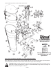
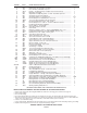
PHOTO # PART # NAME AND DESCRIPTION # NEEDED
1. 984 Grey-Iron Base, w/Bearings, 12” Diameter................................................... 1
2. 894 Bottom part of 3 Pt. Frame - Crossbar ......................................................... 1
3. 174 Fan - 5/8” Bore, 4 Bladed, Lap-over ............................................................. 1
4. 981A Hopper - 12” Diameter Base complete w/screws and decals ...................... 1
5. 873 Back Brace Assembly................................................................................... 1
6. 985 Adjustable Seed Opening Plate, on which Seed Gate operates.................. 1
7. 881 Seed Gate w/connecting Linkage................................................................. 1
8. 925 Seed Gate Guides - 2 used per side............................................................ 2 pr.
9. 403 Hex Head Capscrew w/Flat Washer 1/4” x 1/2” ........................................... 2
9A. 403B 1/4” x 1/2” Hex Head Capscrew w/Lockwasher............................................ 2
10. 404 Round Head Machine Screw - 3/16” x 3/16” ................................................ 4
11. 871 Hex Head Capscrew - 5/16” x 1-1/4” w/Lock Washer and Nut..................... 2
12. 901 Fan Shaft (with Keyway) w/Agitator.............................................................. 1
13. 915 Grease Fittings - 1/4” straight....................................................................... 4
14. 902-14 Gear with 14-Teeth, 5/8” Bore ...................................................................... 1
15. 879 Gear Guard................................................................................................... 1
16. 954 Bushing for Casting - 5/8” x 1”, before S/N #200500 - Grey color ............... 4
16A. 954A Powdered Metal Bushing, after S/N #200500 - Bronze color....................... 4
17. 903 Half-Moon Key - 5/8” x 3/16”, used in gears ................................................ 2
18. 902-18 Gear with 18 Teeth, 5/8” Bore....................................................................... 1
19. 401 Square Head Setscrew - 3/8” x 3/4” ............................................................. 4
19A. 401G 3/8” x 3/8” Socket Setscrew for P.T.O. ......................................................... 1
20. 406 Leather Washer used on Fan Shaft Agitator ................................................ 1
21. 886 Socket Setscrew - 1/4” x 1/4” used in Gears................................................ 2
387 Square Head Setscrew 1/4” - 20 x 3/4” used in fan ..................................... 2
22. 402 Rivet for Handle - 3/16” x 7/8” ...................................................................... 1
367 Rivet for Seed Gauge - 3/16” x 3/4” ............................................................. 1
23. 955 Lower Control Handle................................................................................... 1
24. 882 Seed Gauge - complete ............................................................................... 1
882B 1/4” x 2-1/2” Thumb Screw with Nut (only)................................................... 1
25. 930 Tension Spring w/Bolt, used on Control Arm ............................................... 1
26. 897 Driven Shaft - 5/8” x 6-1/2” (w/Keyway)........................................................ 1
27. 998 Spring Pin - 1/8” x 1” .................................................................................... 1
28. 898 Gal. Shield for Tumbling Shaft ...................................................................... 1
29. 403A Hex Head Capscrew - 1/4” x 1/2”, w/Nut...................................................... 2
30. 414P
Complete Power Take-Off Shaft w/Q.T. Yoke, 1-3/8” Spline, 22-1/2” overall length
... 1
30M. 414MP Tractor End only of Power Take-Off Shaft..................................................... 1
30F. 414FP Broadcaster End only of Power Take-Off Shaft ............................................ 1
31. 415P Complete Shield only, for Power Take-Off Shaft........................................... 1
415FP Shield only for Tractor End of Power Take-Off Shaft .................................... 1
415MP Shield only for Seeder End of Power Take-Off Shaft.................................... 1
32/33/34. 5/16” x 1” Machine Bolt w/Nut and Lockwasher ........................................... 1
35. 989A Seeding Chart Decal .................................................................................... 1
36. 831 Herd Surefeed Decal .................................................................................... 1
37. 408 Truss Head Machine Screw - 3/16” x 3/4” w/Nut.......................................... 3
38. 796 Lid (*Optional equipment)............................................................................. 1
39. 797 Lid Spring (*Optional epuipment) w/Bolt and Nut ........................................ 1
40. 982 Hopper Extension - 18” high, 2 Bu. Capacity (*Optional)............................. 1
41. 408A #10 x 3/4” Phillips Truss Head Machine Screw w/Nut (*Optional)................ 1
42. 994 Space Washers for 5/8” Shaft, used behind Gears and Spring Pin............. VAR.
43. 38P Bearing Retainer for Weasler P.T.O. Shield Only.......................................... 1
47 Bearing Retainer for G & G P.T.O. Shield Only ............................................ 2
44. 46 Nylon Bearing for G & G P.T.O. Shield Only................................................. 1
37P Nylon Bearing for Weasler P.T.O. Shield Only .............................................. 2
46. 843 Cross and Bearing Repair Kit (G & G P.T.O. Shaft Only) ............................. 2
47. 1091 Warning Spinning Blades Decal................................................................... 1
(*OPTIONAL EQUIPMENT, NOT STANDARD WITH BROADCASTER.)
INSTRUCTIONS FOR REMOVAL AND REPLACEMENT OF 954 AND 954A BUSHINGS
1. Remove gears, driven shaft, fan and agitator. NOTE! See instruction for removing gears or driven shaft on page #4.
2. Remove grease fittings.
3. Press out old bushing.
4. The new bushing should be pressed into place by exerting even pressure to the whole bearing edge and pressing it into place.
5. After they are in place, they must be reamed out to a 5/8 I.D. or the shaft will not fit. A reamer is best, but a 3 or 4 flute drill bit will
work if you are very cautious. Do not use a 2 flute drill, as it will chatter and tear up the new bearing.
6. Check to see if shaft will fit bushing.
7. Using a small 1/8” drill, drill bushing through grease fitting hole so grease will get between shaft and bearing. Replace grease fitting.
8. Replace shafts and grease. Every 1 hour of use, regrease the bushing for long life
.
DESIGNS SUBJECT TO CHANGE WITHOUT NOTICE.