
User Manual

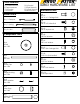

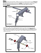


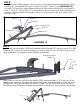


DIAGRAM 5
Lift Arm
(-027)
Lift Arm
(-027)
Lift Arm
(-030
Lift Arm
(-030)
DIAGRAM 4
Drive Tube Assy
(-029)
Cross Bow
(-001)
(not Included
in 40863)
Cross Bow
(-001)
crank tube assy
rear
NOTE:
The rear lift arm bolt will need to be removed to insert crank tube (-026). Install
crank tube (-026) per
[DIAGRAM 5b]
and reinstall lift arm bolt. Bolts must line up
through sleeve in the crank arm.
Coat swaged end of crank tube with E-6000
before assembly to prevent moisture inside.
Shock and Cam Assy
towards front of van
(b)
(e)
(d)
(h)
(k)
(g)
Note: Welded
Spud
E-6000
DIAGRAM
DIAGRAM 5b
crank tube
(-026)
For TECHNICAL SUPPORT Call: 800-343-7486 Monday - Friday 8:00 A.M. to 4:30 P.M. (PST)
E-6000
STEP 1
Install pre-assembled drive tube assembly (-029) into cross bows (-001)
with cam end of the tube to the front of the van. Attach through 3/8" round
holes on edge flange of bow. Use 4 each 3/8" x 3/4" hex bolts (d), 4 each 3/8"
flat washers (b) and 4 each 3/8" lock washers (e) per
[Diagram 4]
. Next, remove
hardware (g) (k) (h) and
coat bolts with E-6000 to seal bolt hole in tube.
Re-insert
5/16" x 2" hex bolts (g), 5/16" flat washer (k) and 5/16" nylock nuts (h) per
[Diagram 5]
and tighten.
Note: Cross bows and gutter mounts are not included in the 40863 kit.