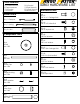
40863 Parts List Ladder Pan Stiffener Item -031 Qty 1 Drive Tube Assembly Item -029 Qty 1 Ladder Pan Item -005 QTY 2 Crank Assembly Item -026 Qty 1 Latch Assembly Item -060 Qty 1 Hold Down Assembly Item -007 QTY 2 Spring/Damper Mount Item -048 QTY 1 E-6000 E-6000 QTY 1 Hold Down Plate Item -008 QTY 2 1-Left 1-Right Hinge Assembly Item -006 QTY 2 Lift Arm Item -030 QTY 1 Welded Spud Lift Arm Item -027 Qty 1
Tools Needed 5/16 Allen Wrench 8' Tape Measure 7/16 Socket 1/2 Socket Motion Pack Qty 1 -Damper Qty 1 -Spring 9/16 Socket 1/2 End Wrench 9/16 End Wrench Small Hammer 40863 HARDWARE LIST Hardware Pack (a) Qty 3 3/8-16 x 1 Carriage Bolt (d) Qty 6 3/8-16 x 3/4 Hex Bolt Qty 2 -Links (c) Qty 2 3/8-16 Nylock Nut Component Pack (b) Qty 8 3/8 Flat Washer Qty 4 Wheel Item -002 Qty 2 Axle Item-003 Qty 4 Wheel Cap Item -004 Qty 4 Flange Bushing Item -036 Qty 8 Nylon Washer Item -038 Qty 2 Bump Stop Item -049
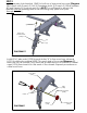
STEP 1 Install pre-assembled drive tube assembly (-029) into cross bows (-001) with cam end of the tube to the front of the van. Attach through 3/8" round holes on edge flange of bow. Use 4 each 3/8" x 3/4" hex bolts (d), 4 each 3/8" flat washers (b) and 4 each 3/8" lock washers (e) per [Diagram 4]. Next, remove hardware (g) (k) (h) and coat bolts with E-6000 to seal bolt hole in tube. Re-insert 5/16" x 2" hex bolts (g), 5/16" flat washer (k) and 5/16" nylock nuts (h) per [Diagram 5] and tighten.
STEP 2 Install rear arm lock bracket (-060) to bottom of rear cross bow per [Diagram 11]. Attach with 2 each 5/16 x 3/4 carriage bolts (f) 2 each 5/16 flat washers (k) and 2 each 5/16 nylock nuts (h). NOTE: You will need to attach this bracket before inserting axle in the following step (axle must pass through bracket). (f) Rear Arm Lock Bracket (-060) (k) (h) DIAGRAM 11 Install 5/16" axle rods (-033) trhough holes "A" in the cross bow channel (-031).
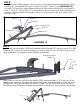
STEP 3 Next, drop ladder pan (-005) over wheels through side slots in pan and line up holes in arms (-027 / -030). (-005) (-036) (-038) (k) (m) Existing Cross Bows and feet (not included in the 40863 kit) Now insert flange bushing(-036) between pan(-005) and arm(-027/-030) as shown in [DIAGRAM 6A]. Now Insert nylon washer(-038) on the outside of lift arm(-027/-030) and flat washer(k), then 5/16 nylock(h) per [DIAGRAM 6A] and tighten. Follow same procedure on each arm. Parts should rotate freely.
FRONT Bump Stop (-049) REAR Bump Stop (-049) Existing Cross Bows (not included in the 40863 kit) Mount (-048) Cam Plate Damper Spring Mounting Location "B" Mounting Location "A" STEP 4 Now insert 2 each bump stops (-049) into 1/2" holes on top of cross bows with flat side facing up. Install spring/damper mount (-048) with offset installed per [DIAGRAM 7]. Fasten using 2 each 3/8 x 1 carriage bolts (a), 2 each 3/8 flat washers (b) and 2 each 3/8 nylock nuts (c).
STEP 6 Install hold down assembly (-007) to the pre-assembled hinge bracket assembly (-006) using 3/8 x 3/4 hex bolt (d) 3/8 flat washer (b) and 3/8 lock washer (e). Next, attach to ladder pan (-005) per [DIAGRAM 2] (location #1 for extension ladders and location #2 for rear step ladders with wider base. For location #1, secure hinge assembly (-006) using 2 each 5/16 flat washers (k) and 5/16 nylock nuts (h).
STEP 8 Install link rods. Depending on the location of the hinge bracket assembly (-006), location #1 will require link rod to attach to hole "E" and "H" per [DIAGRAM 12]. Location #2 (which is step ladder wide end) will require the link rod to attach to hole "F" and "G". Note: Hole "H" is threaded to allow rod end to screw directly into bracket. All other holes will require 1each 5/16 flat washer (k) and 1each 5/16 nylock nut (h).
DIAGRAM 3 Hold Down Plates (-008) STEP 10 With ladder placed against hold down plates (-008) per [DIAGRAM 3] move ladder (front to rear) to a position that allows clamp (-010) to register on ladder side channels in a location that allows (face) to contact the flat on the ladder side channel. Move clamp (-010) so that it is in proper location in hold down assembly (-007). Tighten so 1/8" of stud is extended through nut shown in [DIAGRAM 3d].