
Operations and Maintenance Manual

_
MPR 4.1
Reader Maintenance Instructions
Confidential UM UM360479-100 Revision: Draft B4 Page 93 of 246
© Kapsch TrafficCom Canada Inc. 2022
All information contained herein is proprietary to, and may only be used with express, written permission from, Kapsch TrafficCom Canada Inc.
FILE: UM360479-100 REV B4 DRAFT WIP MPR-4.1 READER OPERATIONS AND MAINTENANCE MANUAL (002).DOCX
05/25/2022 11:18
Kapsch TrafficCom
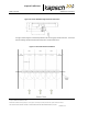
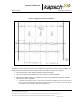
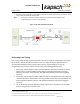
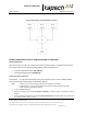
8. Secure the service loop portion of the feedline to the antenna-mounting bracket using the tie wraps. Do not
severely bend or kink the RF feedline cable.
Note: The N type connectors are weather resistant, but should be entirely wrapped in self-
amalgamating tape to ensure a water tight seal.
Figure 5-9: RF Cable Installation Schematic
Performing Lane Tuning
Lane Tuning consists of selecting the frequencies to be used on the Ports and setting the attenuation
for the Ports to control the ERP of the reader. These are configured using the web interface. It is
recommended that Kapsch Services perform lane tuning to properly configure a site. If the
integrator/operator wishes to perform the lane tuning, the following guidelines apply.
• When using multiple adjacent readers, the same FDM Port frequency should not be used on
adjacent lanes, including straddle and shoulder (recommended at least 24ft. separation
between antennas for in-line antennas, 21ft (18ft lateral) between antennas for staggered
antennas).
• When using multiple adjacent readers, TDM Ports that are configured active in the same time
should not be used on adjacent lanes, including straddle and shoulder (recommended at least
24 feet separation between antennas, 21ft (18ft lateral) between antennas for staggered
antennas).
• The TX attenuation should be adjusted to obtain capture zones nominally 8 to 12 ft. (1.83 to
2.44 m.) along direction of vehicle traffic.