
Operations and Maintenance Manual

_
MPR 4.1
Reader Maintenance Instructions
Confidential UM UM360479-100 Revision: Draft B4 Page 92 of 246
© Kapsch TrafficCom Canada Inc. 2022
All information contained herein is proprietary to, and may only be used with express, written permission from, Kapsch TrafficCom Canada Inc.
FILE: UM360479-100 REV B4 DRAFT WIP MPR-4.1 READER OPERATIONS AND MAINTENANCE MANUAL (002).DOCX
05/25/2022 11:18
Kapsch TrafficCom
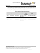
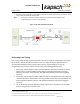
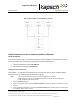
• If the physical lane width exceeds 15 ft.(4.57 m), the lane should be treated as a multi-lane
free flow configuration and multiple antennas are used per lane. The antenna spacings
should be kept at 12 ft separation in each row.
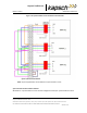
• The same FDM Port frequency should not be used on adjacent lanes, including straddle and
shoulder lanes (recommended at least 24 ft. separation between in-line antennas and 21 ft
for staggered antennas).
• NOTE: It is preferable to use more frequencies where possible to minimize inter-Port
interference due to FDM.
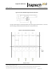
Along track alignment
The capture zone created by an antenna is a function of tuning, tilt angle, antenna used, height and reflective
properties of the site. There is no single value that can be used to define the alignment of the antenna center
to the capture zone. As a guideline nominally 75% of the Capture zone is in front of the antenna center.
Multiple readers
Where multiple readers are on a site, the following additional guidelines apply:
• The readers must be synchronized and running the same frame sequence configuration, or
compatible frame sequence configurations.
Installing Antenna Cables
CAUTION:
Excessive bending or kinking can damage the RF feedline cables. Do not
excessively bend or kink the RF feedline cables while fishing them through
the rigid conduit from the antenna to the Reader enclosure.
1. Place the RF feedline cable(s) in position. Use an appropriate cable type (coaxial or Heliax) to ensure the
RF feedline cable does not produce a signal loss greater than permitted, see Appendix A RF Cable
Specification. Use flexible cable (LMR400 preferred) for the short feedline cable between the circulator and
the antenna
2. Using tie wraps, create a service loop of 6 ft. at both ends of the RF feedline cable(s). Trim the excess
cable length.
3. Install spiral wraps on the RF feedline cable(s) where necessary to protect it from abrasion.
4. Attach the N-Type male connector to the antenna end of the RF feedline cable(s) . Firmly crimp the male
connector.
5. Using a 10in-lb torque wrench, connect the RF feedline cable to the desired MPR 4.1 Port. Using self-
amalgamating tape, wrap the connection to ensure water cannot enter.
6. Using a 10in-lb torque wrench, connect the other end of the RF feedline cable to the antenna. Using self-
amalgamating tape, wrap the connection to ensure water cannot enter.
7. Tie all RF Adapter cables neatly and label both ends of each adapter cable.